
Transformerless Power Supply

The transformerless power supply circuit is a compact and efficient solution for powering low-voltage devices directly from the AC mains supply without the need for a bulky transformer. This type of circuit typically employs a dropping capacitor to limit the current flowing into the load, allowing for a reduced voltage output suitable for various electronic applications.
In designing a transformerless power supply, the selection of the dropping capacitor is critical. The capacitor must be rated for the appropriate voltage and should have a capacitance value that ensures the output voltage remains within acceptable limits for the connected device. The value of the capacitor can be calculated based on the desired output voltage, load current, and the frequency of the AC supply.
Additionally, safety considerations must be taken into account when working with circuits connected directly to the mains. Proper isolation techniques and component ratings must be adhered to in order to prevent electrical shock hazards. The circuit may also include a rectifier, typically a diode bridge, to convert the AC output from the dropping capacitor into a DC voltage, followed by a smoothing capacitor to filter the rectified signal for a more stable output.
Furthermore, the design may incorporate a voltage regulator to maintain a consistent output voltage under varying load conditions. This is particularly important in applications where precise voltage levels are necessary for the proper operation of electronic components.
Overall, while transformerless power supply circuits can be advantageous for their simplicity and size, they require careful design and implementation to ensure functionality and safety.Transformerless Power Supply Circuit Diagram. Selection of the Dropping capacitor and the circuit design requires some technical knowledge and practical experience to get the desired voltage and current 🔗 External reference
Related Circuits
Processor-based systems typically require a voltage supervisor chip to generate a clean reset pulse for the processor whenever a brown-out condition in the power supply is detected. More complex designs that utilize multiple power supplies can become unreliable if...
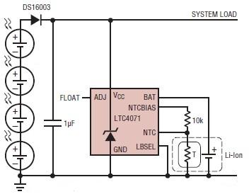
A simple solar-powered battery charger circuit can be designed using the LTC4071 Li-Ion/Polymer Shunt Battery Charger System with Low Battery Disconnect. When VCC reaches the programmed float voltage (4.1V with ADJ floating), the LTC4071 shunts excess current not used...
This circuit utilizes the TA7222AP to amplify audio signals. The cost is only $0.99, and it can provide 5.8 watts with muting control. The power supply can be in the range of 8-12 VDC, making it suitable for applications...
After one has built a QRP transmitter, it would be interesting to know the exact amount of output power. Without a power meter, the peak to peak voltage Vss is measured at a 50-ohm resistance (dummy load) with the...
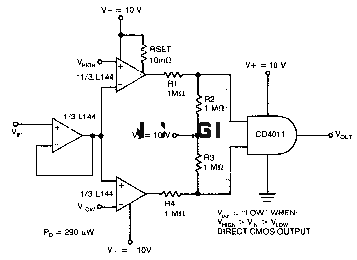
The detector utilizes three sections of an L144 and a DC4011 type CMOS NAND gate to create a very low power voltage monitor. If the input voltage, Vin, is above Vhigh or below Vlow, the output will be a...
This circuit utilizes a 13-volt zener diode (D2) for voltage regulation. Approximately 0.7 volts are dropped across the base-emitter junction of the transistors, resulting in a higher current output of 12.3 volts. The circuit is capable of supplying loads...