
Transistor Bistable Multivibrator or Flip-flop

A bistable multivibrator is a fundamental electronic circuit that has two stable states and can maintain its state indefinitely until triggered to switch states. This device is commonly referred to as a bistable flip-flop and can be implemented using either discrete transistors or integrated logic gates. The bistable multivibrator serves as a memory element in digital electronics, allowing the storage of binary information.
In a typical configuration using transistors, the bistable multivibrator consists of two cross-coupled NPN or PNP transistors. Each transistor is connected to the collector of the other, forming a feedback loop. The circuit can be set into one of its stable states by applying a trigger signal to the base of one of the transistors. This action causes one transistor to turn on fully, while the other turns off, thus establishing a stable state.
When the circuit is in one state, it can be switched to the opposite state by applying a trigger signal to the other transistor's base. The transition between states is characterized by a brief period of instability, during which the circuit will settle into the new stable state. The output of the bistable multivibrator can be taken from the collectors of the transistors, providing a digital high or low signal that corresponds to the current state of the circuit.
Alternatively, a bistable multivibrator can be constructed using logic gates, such as NAND or NOR gates. The configuration of these gates allows for the same feedback mechanism as in the transistor version, enabling the circuit to toggle between its two stable states. The advantage of using logic gates is that they can be easily integrated into larger digital systems, facilitating compact designs and reducing the number of discrete components required.
In both implementations, the bistable multivibrator is a critical building block in digital circuits, utilized in applications such as data storage, flip-flops in memory devices, and state machines in sequential logic designs. Understanding the operation and design of bistable multivibrators is essential for those involved in electronics and digital system design.Electronics Tutorial about Bistable Multivibrator also known as the Bistable Flip-Flop or Two-shot Multivibrator constructed from Transistors or Logic Gates.. 🔗 External reference
Related Circuits
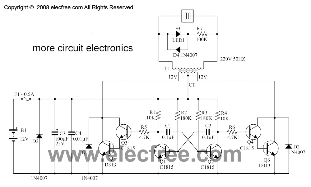
This is a small inverter rated at 30 watts. It converts DC voltage from a 12V battery to AC voltage of 220V-230V at a frequency of 50Hz, which is the same electricity used in households. It can power 2-3...
Simulation schematic for an astable multivibrator. Parameters: Vcc = 24V, Vol = 1V, Voh = 21V. The power supply is Vcc, with connections from Vcc to ground. The time constant is determined by R1 and the capacitor C1, where...
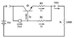
This application datasheet article includes sections that discuss the practical current booster circuit technique, which involves a conventional circuit using a Constant Current Load (CLD) and a current boosting circuit technique. It covers the analysis of the booster circuit...
The basic bipolar transistor (BJT) version of an astable multivibrator has two outputs that repeatedly change state at a rate determined by the time constants of its feedback network. Although largely superseded by its equivalent op-amp or timer IC...
What exactly is a multivibrator? I suppose one definition would be 'a circuit which has several states'. This will do for now, it's quite loose so leaves plenty to the imagination! Conventional multivibrators have only two stages and come...
The following circuit illustrates a VHF pre-amplifier circuit diagram. This circuit utilizes the BFS17 transistor. Features: designed for VHF applications. The VHF pre-amplifier circuit is essential for enhancing weak radio frequency signals in the VHF (Very High Frequency) range, typically...