
mini inverter 10w 30w by transistor d313

1. The 50Hz frequency is crucial; if it is too low, the airflow will be weak, and if it is too high, the coil will respond prematurely, failing to maintain a stable operation.
2. The waveform balance is also important; household electricity typically shows a waveform with high-low peaks, which can be replaced with a square wave.
To convert a 12V battery to 220V AC at 50Hz, an inverter circuit is employed. The basic operation can be illustrated with a block diagram. The process begins by applying the 12V battery to a 50Hz frequency generator that produces a square waveform. The current then flows through an amplifier to drive the primary coil of a transformer, inducing current in the secondary coil to produce 220V AC at 50Hz, ready for use with the air pump.
The oscillation generator circuit is selected to utilize dual transistors, similar to a 2-LED alternating flasher circuit. Capacitors C1 and C2 are used to set the output frequency, and they should have the same value; in this case, a 0.1µF capacitor is chosen for its availability. The current amplifier circuit enhances the signal from the frequency generator before it drives the transformer, which is a critical section of the circuit. A 2SD313 transistor is initially selected due to its ability to handle high currents (up to 1A at 12V), although it has low gain, necessitating the addition of another current amplifier transistor.
The circuit is configured in a Darlington arrangement to achieve high gain and high input impedance, which significantly reduces noise. The transformer used has a center tap, allowing for alternating operation of two amplifier sets with identical electrical characteristics. When Q1 conducts, Q2 is inactive, allowing current to flow through resistors R4 and R6, providing bias current to Q4 and Q6, which then conduct. Conversely, when Q1 is off, Q2 conducts, and current flows through R1 and R5, triggering Q3 and Q5 to replace Q4 and Q6. This alternating current flow through the transformer coils creates high power output.
Transistors Q5 and Q6 serve as high-output drive amplifiers; the 2SD313 is chosen for its collector current capability exceeding 1A and cost-effectiveness, although alternatives like H1061 or TIP41 may be used for higher performance. Resistors R5 and R6 provide bias currents to the bases of Q3, Q5, and Q4, Q6, facilitating their alternating operation. A diode (D3) is included for protection against incorrect polarity connections; it allows negative voltage to flow through it to safeguard the circuit, although it may short-circuit, leading to a blown fuse (F1). An LED (LED1) indicates when the power is on, illuminating when 220V at 50Hz is present, with resistor R7 limiting current to the LED.This is small inverter on 30 watts, It converts DC voltage from 12V battery to AC 220V-230V at 50Hz which is electricity same use in your house. It can provide 2-3 Air pump or other. You will like them because so cheap and easy to builds. Then, what is it required. When look at its bottom will see that a special feature as Figure 2 notice Importan ce : Use for voltage of 220 volts, Frequency of 50Hz(AC:220V/240V 50Hz) And use AC electrical power of 2. 8 watts (power:2. 8W) The air Pump consists of a rubber ball (similar to a pneumatic for bicycle tire) to generated to output.
By The driving force between the magnet and electromagnet. Then, try to apply AC 220V to them will see that Permanent magnet vibrates very fast, so Pumping the air out. Near the same that have a similar device is a transformer coil pack, but with only a single coil. It is the electromagnet there. 1. The 50Hz frequency: has very importance, if too low frequency Strong winds are not very and when high frequency the coil will respond before, until stationary to do.
2. The Waveform balance is best perfect, When see in home electricity waveform will see that has peaks to peaks high-low. Which we can use other waveform instead so may will use the square wave. As above, we have to convert 12V battery to 220V AC 50Hz. by an inverter circuit. Which we can draw the simple block diagram As Figure 4. When apply 12-volts battery to the 50Hz frequency generator on square waveform. After that, current will flow through amplifier up. To drive the primary coil of transformer and Inductor current to the secondary coil. into the 220V AC 50 Hz as you need ready to use with the air pump. In conditions, I select the oscillated generator circuit by dual transistors. As used an 2 led alternating flasher circuit. As Figure 5 is the 2 led alternating flasher circuit. 4. C1, C2 are capacitors that set frequency output, should same value, so calculate only C1 in single. In this case, I choose a 0. 1uF because is medium, easy to find. Next, the current amplifier circuit by increasing signal from the frequency generator rises up before drive the transformer next, this is importance section.
First of all, I think to use 2SD313-transistor only one. Because Can tolerate high current of about 1A. ( at 12V). But has disadvantages are low gain to have add increase current transistor other one. So is simple current amplifier circuit as Figure 7. When is set as this Darlington form, cause very high gain and have high input impedance, so reduce noise so much. Because we need waveform that has high power both positive and negative. So should use transformer that has center trap and use two amplifier set, that has same electricity feature.
By Each set is alternately working, when Q1 conduct current, result to Q2 not works. So current flow through R4, R6 provide current bias to Q4, Q6 conducts current. Result have current from the battery to transformer coil. But when Q1 stop cause Q2 works so has current flow through to R1, R5, to provide current trigger to Q3, Q5 conduct current replace Q4, Q6. Thus current from battery so flow through other transformer coil instead. Cause electricity inductance through the transformer switch between positive and negative with high power.
2. Q5, Q6 are high output drive amplifier transistors. I selected a 2SD313 because high current collector more than 1A and cheap. You can use H1061 or TIP41 quality better (high current and voltage) 3. R5, R6 are resistors to provide current to bias the base of Q3, Q5 and Q4, Q6, which they will work alternately as principle above. In this case I so choose them are 4. 7K. - D3 is diode protection if connected in wrong polarity. The negative voltage will flow through D3 instead. Makes circuit safe. But D3 may be short and F1-fuse blown instead. - LED1 is power on display when have the power : 220V 50Hz completely. The R7 acts to reduce current to LED1. And there is 🔗 External reference
Related Circuits
A 40-watt fluorescent tube lamp or two 20-watt tubes in series will be driven by this circuit. The transformer is wound on a ferrite rod with a diameter of 10 mm and a length of 8 cm. The circuit described...
This circuit is designed to convert 12V DC into 220V AC. It utilizes a 4047 integrated circuit to generate a 50Hz square wave, which is then amplified for current and voltage using a step-up transformer. The fundamental relationship between...
The circuit utilizes an integrated circuit (IC) type multivibrator as the oscillator for alternating current, operating at approximately 60 Hz. The 7400 IC is employed for this purpose, although the 7404 IC can also be used. The oscillator signal...
This simple LED flasher circuit will alternately turn ON and OFF two LEDs. The first LED will illuminate when the second LED is OFF for a certain duration, and then the process will repeat. The LED flasher circuit operates using...
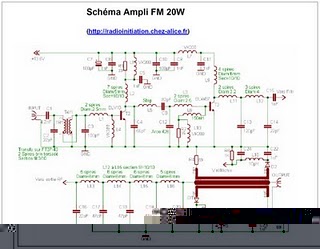
The following circuit illustrates an RF amplifier designed for FM frequencies ranging from 88 to 108 MHz with a broadband configuration. This circuit utilizes the BLV10 transistor. The RF amplifier circuit operates within the FM broadcast band, which is crucial...
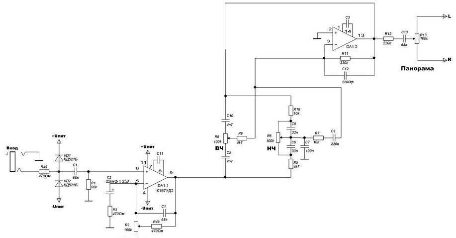
The four main input channels are identical and feature independently adjustable input sensitivity, tone, and sound panning. The fifth input is a linear channel. Despite its inexpensive and basic design, the Mini Audio Mixer "Impulse MM-04" performs satisfactorily. The Mini...