
transistor circuit for counting wheel rotations

In circuit design, it is crucial to understand the fundamental components and their interactions. A basic circuit typically includes resistors, capacitors, inductors, diodes, and transistors, each serving specific functions. Resistors limit current flow, capacitors store and release electrical energy, inductors oppose changes in current, diodes allow current to flow in one direction, and transistors act as switches or amplifiers.
When designing a circuit, one must start with a clear objective, such as creating a power supply, amplifier, or oscillator. The schematic diagram serves as a blueprint, illustrating how components are connected. Proper labeling of each component and adherence to standard symbols is essential for clarity.
Additionally, understanding Ohm's Law (V = IR) and Kirchhoff's Laws is fundamental for analyzing circuit behavior. Simulation tools can be utilized to test designs before physical implementation, allowing for adjustments and troubleshooting without the risk of damaging components.
In summary, effective circuit design requires a solid grasp of electronic principles, careful planning, and thorough testing to ensure functionality and reliability.Hey guys, I am new to the forum. I hope this is the right section. Sorry if I ask some dumb questions, I am new to circuit design. This is for my.. 🔗 External reference
Related Circuits
The ISO103 ripple reduction circuit features an output circuit combined with an RC high-pass filter designed to filter out output ripple without impacting the direct current (DC) characteristics. Under specific conditions, the circuit is capable of reducing an 800...
The digital scoreboard circuit is designed to display numerical values ranging from 0 to 9 on a common anode 7-segment display. The circuit employs a 7-segment driver integrated circuit (IC), specifically the 74LS47 or 74LS247. A 555 timer IC...
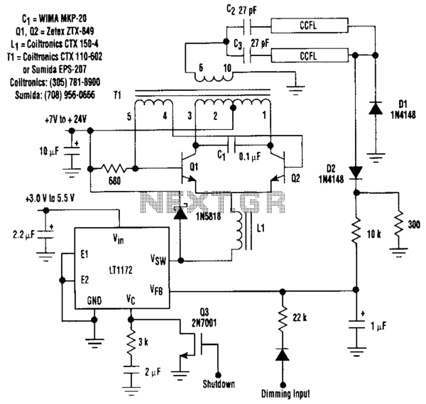
This circuit is a 92%-efficient power supply for cold-cathode fluorescent lamps (CCFLs), which are used to backlight LCDs in portable equipment. The efficiency depends heavily on the component types, particularly C1, Q1, Q2, L1, and T1, whose manufacturers are...
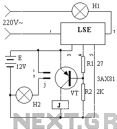
The device circuit operates as illustrated in Figure 11. Power outages are a common occurrence, but in certain situations, maintaining power is critical, such as during ongoing surgeries. The circuit employs a simple design that is fully automated. When...
This toggle circuit utilizes two 555 timers configured as inverters. Pins 2 and 6 serve as the threshold and trigger inputs for the first timer, while pin 5 provides the output. The output at pin 5 will consistently reflect...
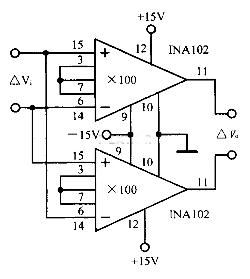
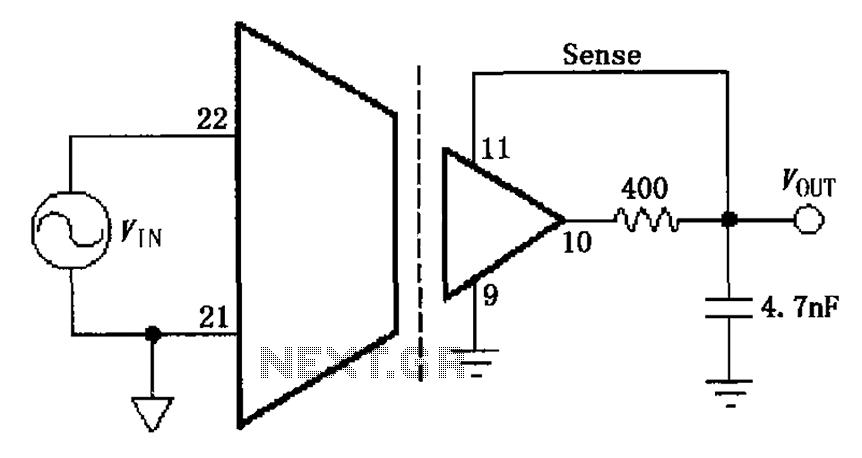
A differential input differential output amplifying circuit diagram. A differential input differential output (DIDO) amplifier is a type of operational amplifier configuration that is designed to amplify the difference between two input signals while rejecting any signals that are common...