
Transistor LED flasher

The circuit's green wires connect to the LEDs, which can be mounted on a circuit board for certain applications. An example of a more power-consuming circuit is provided for variable flash rates, useful for strobe circuits, and can serve as a remote control for strobes with a remote input. The components R1, R2, C1, and the supply voltage determine the flash rate. A regulated power supply enhances the stability of the flash rate. For variable rates, R1 can be replaced with a 1 megohm potentiometer in series with a 22k resistor. The duty cycle is influenced by the ratio of R1 to R2; a low R1 relative to R2 yields a near 50 percent duty cycle, which is ideal when using both LEDs. Conversely, a low R2 compared to R1 results in a duty cycle below 50 percent, conserving battery life or creating a strobe effect when only LED 1 is active.
To protect the NE555 timer chip from damage caused by reverse polarity, a diode can be placed in series with one supply lead. Resistors R3 and R4 limit current through the LEDs, typically set to a maximum of 20mA, with values selected according to the supply voltage; 470 ohms works well for 9-12 volts, while lower voltages require reduced values. Various kits for building this circuit are available from Rainbow Kits and RadioShack, including options with different LED configurations. For instance, the standard kit includes two 5mm red LEDs (catalog number 990-0067), while others feature a mix of colors and sizes. Components for building the circuit can also be purchased at local RadioShack stores, including circuit boards.
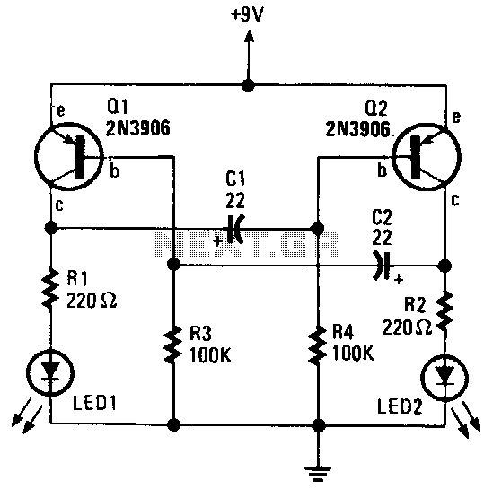
In a practical application, a miniature strobe circuit can be created using a 250k potentiometer in series with a 4.7k resistor for R1, setting the upper flash rate limit, and a 2.2k resistor for R2 to establish a short duty cycle. In this configuration, LED 2 and R4 are omitted, utilizing two white LEDs in series for LED 1 without R3. The circuit operates on a 9V battery. The introduction of the LM3909 LED flasher chip by National Semiconductor in the late 1970s marked a significant development in LED flashing technology, garnering attention from electronics enthusiasts and hobbyists.By simple, I mean that these circuits only flash one or two LEDs. This is opposed to the light chaser circuits that can flash four or more. Of course, the simplest LED flasher is simply to use a flashing LED. The problem with that approach is you have no control over the flash rate, but it does have its use for eye catching displays for selling st uff. The circuits below give you that control, plus they can flash two LEDs alternately. This circuit has a lot going for it. For one thing, it only consists of two transistors, two capacitors and four resistors. That also means it consumes very little power. You can control the flash rate by changing the size of the 100k resistors (100k makes for a pretty slow rate). You can also control the duty cycle by using resistors of different values on the two sides. The 470 ohm resistors control the current through the LEDs. Normally you want to limit this to 20mA, but to conserve battery power, you may need to limit it even further.
You can also connect several LEDs in series, instead of using only one for each side. With red LEDs (1 per side) and the values shown, the circuit draws about 11mA. Here`s what the actual circuit looks like: On this circuit, the green wires connect to the LEDs, but you can mount them on the actual circuit board for some applications. The picture is about twice actual size. Here is an example of the use of this circuit: This circuit consumes more power, but it`s advantage is when you need a variable flash rate, like for strobe circuits.
You can actually use this circuit as a remote control for strobes that have a remote input. Of course, it has many other applications besides strobes. R1, R2, C1 and the supply voltage determine the flash rate. Using a regulated power supply will do much to insure a stable flash rate. For a variable flash rate, replace R1 with a 1 megohm pot in series with a 22k resistor. The duty cycle of the circuit (the percentage of the time LED 1 is on to the time it is off during each cycle) is deterimed by the ratio of R1 to R2. If the value of R1 is low in relationship to R2, the duty cycle will be near 50 percent. If you use both LEDs, you will probably want a 50 percent duty cycle. On the other hand, if R2 is low compared to R1, the duty cycle will be less than 50 percent. This is useful to conserve battery life, or to produce a strobe type effect, when only LED1 is used. The NE555 timer chip can be damaged by reverse polarity voltage being applied to it. You can make the circuit goof proof by placing a diode in series with one of the supply leads. The purpose of R3 and R4 is to limit current through the LEDs to the maximum they can handle (usually 20 milliamps).
You should select the value of these according to the supply voltage. 470 ohms works well with a supply voltage of 9-12 volts. You will need to reduce the value for lower supply voltages. Rainbow Kits offers several kits to build the above circuit. You can also order these kits from RadioShack. com. The Radio Shack catalog numbers (and web pages) are as follows: standard kit with two 5mm red LEDs, (990-0067), kit with two red, two green and two yellow 3mm LEDs, (990-0063), kit with jumbo green LEDs, (990-0048), kit with jumbo red LEDs, (990-0049). You can also buy all the parts to build the circuit at your local Radio Shack store, including a circuit board (276-159B).
I have built a miniature strobe circuit as follows. Use a 250k pot in series with a 4. 7k resistor for R1. The 4. 7k resistor sets the upper flash rate limit. Use 2. 2k for R2. That sets a really short duty cycle. For this circuit, you don`t use LED 2 or R4. For LED 1, I used a two Radio Shack white LEDs in series and no R-3. The circuit runs on a 9 v battery. In the late 70s, National Simiconductor came out with the LM3909 LED flasher chip. Many of the electronics magazines made a big deal about it at the time, and I got one from Radio Shack, experime 🔗 External reference
Related Circuits
This analyst is a sensitive instrument in the frequency changes and width of an acoustic signal. Thus, the brightness of the LED that turns on each moment is proportional to the signal width, while the color is proportional to...
A LED is used to indicate when a DC voltage reaches 5 volts or more. The LED should be fully illuminated at 5 volts and not dim at 4.5 volts or lower. The circuit should be constructed using discrete...
The LT1932 is a fixed frequency step-up DC/DC converter designed to operate as a constant-current source. Because it directly regulates output current, the LT1932 is ideal for driving light emitting diodes (LEDs) whose light intensity is proportional to the...
This is a 220V LED flasher circuit designed as a reliable alternative to thermally activated switches used for flashing Christmas tree lamps. It is a cost-effective and easy-to-assemble circuit. The components include R1 (100K), R2 (1K), R5 (1K), R3...
The alternating LED flasher is a two-transistor oscillator with LEDs connected to the collector of each transistor, allowing them to light in sync with the circuit's oscillations. The alternating LED flasher circuit utilizes a two-transistor oscillator configuration, which is a...
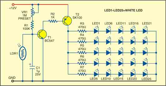
This sunlight-controlled lamp utilizes a light-dependent resistor (LDR) as the sunlight sensor and comprises a total of 25 high-brightness white LEDs. Each row of LEDs is connected in series with separate resistors. The operation of the circuit is straightforward....