
Simple continuity checker

The described circuit functions as a resistance tester that utilizes a multivibrator configuration to generate audio tones based on varying resistance levels. The primary components, Q1 and Q2, are configured as a bistable multivibrator, which produces oscillations at a frequency determined by the resistance connected to the test points. The circuit is capable of measuring resistances in the range of hundreds of kilohms while maintaining sensitivity to small changes in resistance, allowing for the detection of variations as minor as tens of ohms, particularly in low-resistance scenarios.
The output stage, comprising transistors Q3 and Q4, is designed to amplify the oscillating signal generated by the multivibrator. This amplified signal is then used to drive a small loudspeaker or a telephone earpiece, converting the electrical oscillations into audible tones. The frequency of the output tone directly corresponds to the resistance being measured, providing an intuitive auditory indication of resistance levels.
In practical applications, this circuit can be utilized for testing and troubleshooting electrical components, ensuring that resistance values fall within specified ranges. It can be particularly useful in scenarios where quick assessments of circuit integrity are necessary, such as in maintenance and repair tasks. The simplicity and effectiveness of this resistance tester make it a valuable tool in electronics engineering and related fields.The pitch of the tone is dependent upon the resistance under test. The tester will respond to resistance of hundreds of kilohms, yet it is possible to distinguish differences of just a few tens of ohms in low-resistance circuits. Ql and Q2 form a multivibrator, the frequency of which is influenced by the resistance between the test points.
The output stage Q3 and Q4 will drive a small loudspeaker or a telephone earpiece.
Related Circuits
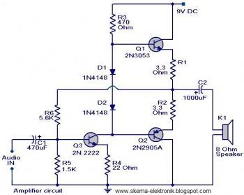
The initial section of the circuit is a preamplifier that utilizes transistor Q1 (2N2222). The collector of transistor Q3 is connected to the base of transistor Q2 (2N2905A), which creates a complementary symmetry pair with Q3 (2N3053). The amplified...
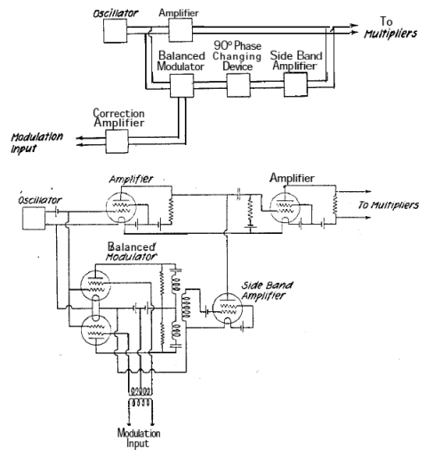
A system is being developed to transmit in the FM band. The oscillators have already been constructed to facilitate transmission across multiple frequencies. The design of an FM transmission system involves several key components, including oscillators, modulators, amplifiers, and antennas....
This circuit diagram indicates when the input voltage deviates from two defined limits, V1 and V2. The limits are adjustable, and the circuit is designed to trigger the adjustable window. The supply voltage, Vcc, must be at least 2...

This is a simple XTal tester circuit. T1 and XTal have formed an oscillator. C1 and C2 are voltage divider for oscillator. if the XTal is safe, the oscillator will work well and its output voltage will be rectified...

This continuity checker is built around an LM339 quad comparator with open-collector outputs, designed to eliminate false readings caused by coils or low-resistance devices in a circuit. U1 is a comparator that acts as a sensing amplifier for the...
This continuity tester circuit allows for the examination of PCB track failures without the need to visually inspect the routing of the tracks, which can often be frustrating. The continuity tester circuit is designed to facilitate the detection of faults...