
Transistor Tester

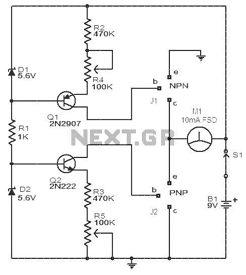
The circuit utilizes a 555 timer configured in astable mode to generate a continuous square wave output. This square wave is used to drive a series of transistors, specifically Q1 through Q4, which serve as switching elements in the circuit. The operation of the 555 timer is critical as it sets the frequency and duty cycle of the output signal, influencing the behavior of the connected transistors.
LED1 and LED2 are indicators that provide visual feedback on the operation of the transistors. When an NPN or PNP transistor is connected to the test terminals, the corresponding LED will illuminate, indicating that the transistor is functioning correctly. The presence of LED1 signifies that the NPN transistor is conducting, while LED2 indicates that the PNP transistor is operational.
Additionally, LED3 and LED4 serve as diagnostic tools for assessing the condition of the transistors. If these LEDs illuminate with the same brightness as LED1 and LED2, it confirms that the tested transistor is functional and correctly biased. However, if LED3 and LED4 exhibit a brightness that surpasses that of LED1 and LED2, it indicates a short circuit condition in the transistor, suggesting that it has failed and is no longer performing its intended function.
The circuit design emphasizes the importance of clear visual indicators for troubleshooting and verifying the integrity of transistor operation. Proper biasing and connection of the transistors are essential for accurate results, and the use of LEDs provides an immediate visual representation of the circuit's status. This schematic can be used in various applications, including educational demonstrations and practical testing of transistor functionality. A 555 timer drives Ql through Q4 with a square wave. LED1 and LED2 light when an npn or pnp transistor respectively, are connected to the text terminals. If LED3 and LED4 light equally as LED1 and LED2, the transistor is functional. If LED3 and LED4 are brighter than LED1 or LED2, the transistor is shorted.
Related Circuits

The VU meter operates in conjunction with the integrated amplifier circuit. The audio signal is processed by the audio amplifier circuit, which drives the VU meter to display the audio level. The VU meter circuit is designed to visually represent...
Our CONTINUITY TESTER gives an audible indication of continuity between the probes so you can keep your eyes on the probe tip. Secondly its response-time is very short so that you can make lots of tests very quickly while...
This circuit is a simple device for testing the hfe (current gain) of both PNP and NPN transistors, with the capability to measure hfe values as high as 1000. It operates using two constant current sources formed by transistors...
This circuit allows for the testing of quartz resonators within a frequency range of 32 kHz to 24 MHz. The operational status of the quartz resonator is indicated by a diode signaling an LED and an acoustic signal. The circuit...
If you have a servo and you want to test it but do not have a remote control or a dedicated tester, you can create a simple schematic for a servo tester. This circuit is based on a 555...
This circuit is basically simple and easy to build, it uses two transistors as active components and a few passive components like resistors, capacitors and two LEDs. The circuit makes use of the MPS2222 transistor. You can use any...