
crystal tester

The circuit is designed to facilitate the evaluation of quartz resonators, which are critical components in various electronic applications, particularly in timing and frequency control. The testing process involves applying an input signal to the quartz resonator and measuring its response to determine if it operates within the specified frequency range.
Key components of the circuit include a signal generator, which produces a range of frequencies from 32 kHz to 24 MHz, and an oscillator circuit that engages the quartz resonator under test. The output of the resonator is monitored through a diode that drives an LED indicator. When the resonator is functioning correctly, the LED lights up, confirming the presence of a valid oscillation. Additionally, an acoustic signal is generated, providing an audible confirmation of the resonator's operational status.
The circuit may also incorporate a variable resistor to adjust the sensitivity of the detection circuit, allowing for the testing of resonators with varying quality factors (Q). A capacitor may be included in the design to filter out noise and stabilize the output signal, ensuring accurate readings.
Overall, this circuit serves as an invaluable tool for engineers and technicians involved in the design and maintenance of electronic systems that rely on quartz resonators. Its straightforward design and dual indication method (visual and auditory) enhance usability and efficiency in testing procedures.This circuit enables you to test quartz resonators at the range values from 32kHz to 24MHz. Confirmation of good state of quartz resonator is done by diode signalling LED and acoustic signal.. 🔗 External reference
Related Circuits
A DC capacitor tester circuit diagram utilizing a 555 timer is presented. The tester includes a pulse generator, a one-shot circuit, a DC amplifier, and a meter indication circuit. It is capable of measuring capacitors ranging from nanofarads (nF)...
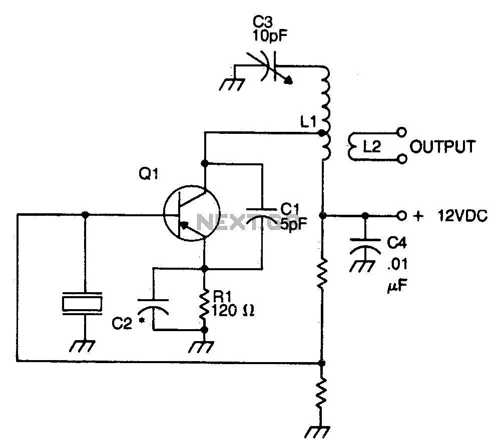
The crystal element in this circuit is connected directly between the base and ground. Capacitor C1 is utilized to enhance feedback due to the internal capacitances of the transistor. This capacitor should be positioned as close as possible to...
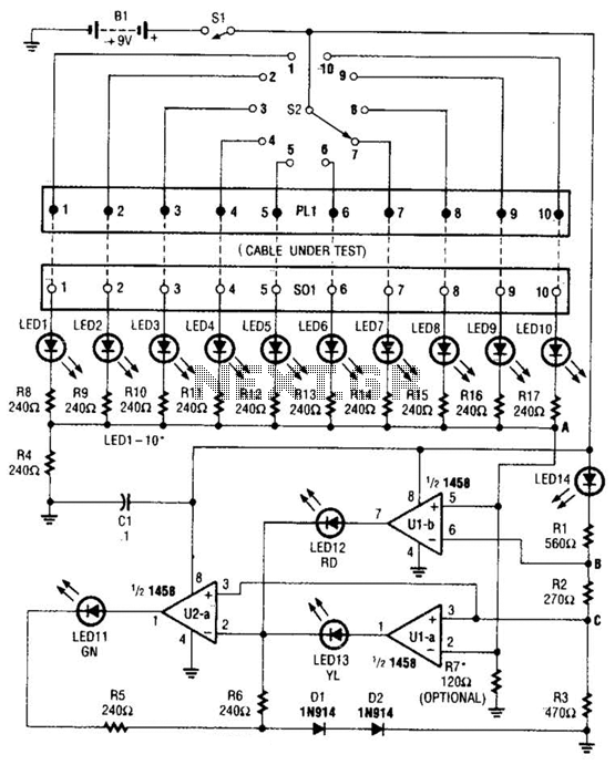
The cable tester utilizes two operational amplifiers (op-amps) configured as window comparators to detect short or open circuit conditions. A third op-amp comparator is employed to indicate a properly functioning circuit, meaning it is neither open nor shorted. Colored...
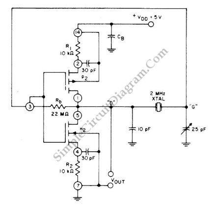
This circuit is a 2 MHz crystal oscillator utilizing a CMOS transistor pair. It is particularly suitable for applications in digital watches and clocks due to its low power consumption. The oscillator is constructed by connecting a CMOS transistor...
If you have a servo and you want to test it but do not have a remote control or a dedicated tester, you can create a simple schematic for a servo tester. This circuit is based on a 555...
Testing loudspeakers is covered in some detail in the passive crossover article, but it is irksome at best to have to fiddle about with clip leads and components lying all over the workbench. This simple project is intended to...