
Three-Level Audio Power Indicator

The audio power output indicator circuit provides an effective means of monitoring the power levels of audio amplifiers. The circuit's design incorporates an input buffer (IC1A) that ensures a stable signal is fed into the subsequent voltage comparators. These comparators are calibrated to trigger at specific voltage thresholds corresponding to the desired power output levels, which are indicated by the illumination of LEDs.
The variable DC voltage generated by resistor R5 and capacitor C4 plays a crucial role in smoothing the input signal, allowing for accurate voltage comparison. This smoothing action helps to mitigate fluctuations in the input signal that could lead to erroneous readings. The clamping of the supply voltage to 5.1V ensures that the operational amplifiers and the trimmers operate within a stable voltage range, enhancing the reliability of the circuit.
In practical application, the circuit is connected to an audio amplifier output. The use of an oscilloscope or audio millivoltmeter allows for precise measurement of the output voltage, facilitating the adjustment of the circuit settings. The adjustment of trimmer R2 is particularly important, as it sets the threshold for LED D3, which visually indicates when the amplifier reaches the specified output power level.
Overall, this circuit is an invaluable tool for audio engineers and enthusiasts, allowing for real-time monitoring of amplifier performance and ensuring optimal operation within desired parameters. Its portability and simplicity make it suitable for various applications, from home audio setups to professional sound reinforcement systems.This circuit is intended to indicate the power output level of any audio amplifier. It is simple, portable, and displays three power levels that can be set to any desired value. For a standard HiFi stereo power amplifier like the 25W one described in these pages, the power output values suggested are as followings: The above values were chosen for easy setup, but other settings are possible. IC1A is the input buffer, feeding 3 voltage comparators and LEDs drivers by means of a variable dc voltage obtained by R5 and C4 smoothing action. In order to achieve setting stability, the supply of IC1 and trimmers R6 & R7 is reduced and clamped to 5.
1V * Connect the generator to the amplifier input and the Audio Power Indicator to the output of the amplifier, in parallel with the oscilloscope probe or the audio millivoltmeter input. * Example: set the output of the 1KHz sinewave generator to read 14V on the audio millivoltmeter (24.
5W 8 Ohms). Set R2 until D3 illuminates, and be sure that D3 turns-off when diminishing a little the generator`s output. 🔗 External reference
Related Circuits
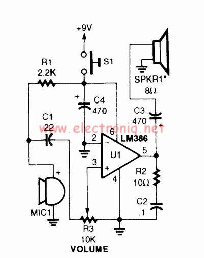
A voice amplifier can be designed using the LM386 power amplifier, which is intended for low voltage consumer applications. This simple circuit features variable gain and volume control. The gain is set internally to 20 to minimize the number...

The circuit features a sensitive LM358-based comparator, IC1A, which keeps the monostable IC2A (a 4538) activated as long as an audio signal is detected at the input. The input signal is taken from the hot side of the loudspeaker...
One design employs the exit transistor technology of V-MOSFETs. These transistors provide numerous advantages over standard bipolar transistors, including high speed, thermal stability, and low distortion. V-MOSFETs, or Vertical Metal-Oxide-Semiconductor Field-Effect Transistors, are a specific type of MOSFET that utilizes...
Measure the voltage across the 1k resistor connected to the input stage and Vcc. The DC voltage should be approximately 2 volts, or 2 mA of current flowing through this resistor. For instance, if Vcc is at 24 volts,...

This 15V variable power supply electronic project is designed using 2N3055 transistors. The output voltage of this variable power supply can be adjusted in the range between 1.5 and 15 volts. This 2N3055 15V variable power supply can provide...
Here a simple design for an attractive tone. They operate on a passive principle, ie without amplification. The circuit only weakened and therefore require no power. As can be seen, the circuit is built with two T-filters in the...