
Triac Dimmer Circuit

The simple triac light dimmer circuit operates by controlling the phase angle of the AC voltage applied to the load, which in this case is an incandescent lamp or a ceiling fan. The primary components of the circuit include a triac, a diac, a potentiometer, and a few passive components such as resistors and capacitors.
In the circuit, the triac acts as a switch that can turn on and off at specific points in the AC voltage cycle. The diac is used to provide a triggering mechanism for the triac; it remains off until the voltage across it reaches a certain threshold, at which point it conducts and triggers the triac. The potentiometer allows the user to adjust the phase angle at which the triac is triggered, effectively controlling the amount of power delivered to the load.
The circuit is connected directly to the AC mains supply, and safety precautions must be taken during construction and use. It is advisable to use components rated for the appropriate voltage and current levels to prevent overheating and potential failure. Additionally, the circuit should be housed in a suitable enclosure to prevent accidental contact with live components.
When using this dimmer circuit for ceiling fans, the design may need to be adjusted to account for the inductive nature of the fan motor, which can affect the performance of the triac. Proper selection of components and careful tuning of the circuit may be required to achieve optimal results.
Overall, this simple triac light dimmer circuit provides an effective solution for controlling the brightness of incandescent lamps and the speed of ceiling fans with minimal complexity and cost. The circuit of a simple triac light dimmer shown below can be used for dimming incandescent lamps directly from AC mains. The circuit is very easy to construct and uses very few components. The pot is used for controlling the load power or the intensity of the light. The circuit can be also used for controlling ceiling fan speeds. 🔗 External reference
Related Circuits

A diode is utilized in a temperature sensor application circuit. Silicon diodes VD1 and VD2 serve as the temperature sensors, exhibiting a temperature coefficient of silicon diodes. The circuit includes a constant current source, VT1, which provides a steady...

This is a universal version of the four-digit alarm control keypad. The design has been modified to free up the relay contacts, allowing the circuit to function as a general-purpose switch. A single pole changeover (SPCO) or single pole...
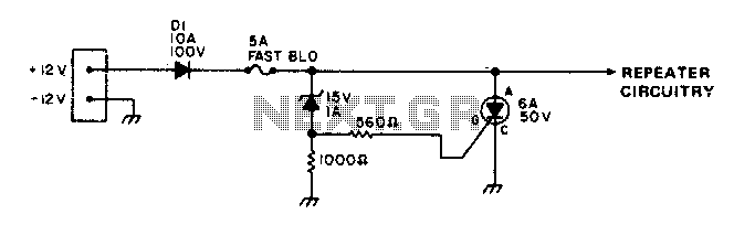
To protect portable emergency power repeaters from reverse or excessive voltage, diode D1 prevents damage from incorrect polarity, while the zener diode voltage sets the maximum voltage that can reach the rest of the circuitry. Additionally, a fast-blowing fuse...

This is a classic design of a 35 W final amplifier utilizing two EL34 tubes in a push-pull configuration, developed by Siemens and Halske. The design dates back to March 24, 1953, and is identified by the code SV410/1....

Half of a Motorola MG14538B dual precision retriggerable monostable multivibrator is utilized to create an extended on-time timer circuit. This type of circuit can function as a switch debouncer. Such circuits are commonly implemented in digital applications, where every...
This circuit utilizes a 555 timer integrated circuit (IC) to function as an alarm system designed to deter theft of personal belongings, such as luggage, or to prevent unauthorized entry into a residence. The alarm is activated when a...