
TRIAC Dimmer LED Driver Reference Design

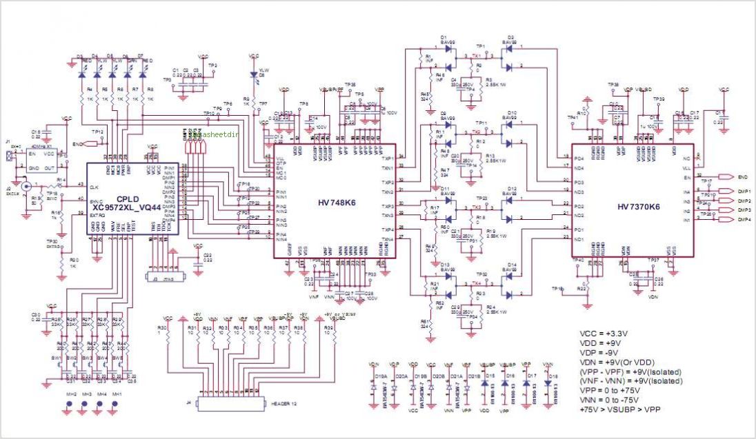
The design features a power conversion circuit that efficiently transforms high-voltage AC input to a suitable output for driving multiple LEDs. The input voltage range of 90V to 135V AC allows for flexibility in various applications, particularly in lighting systems where high voltage is prevalent. The LM3445 is a highly integrated LED driver IC that includes features such as current regulation, which is essential for maintaining consistent brightness across the series-connected LEDs.
The average current of 300 to 600 mA is adjustable, allowing for customization based on the specific LED characteristics and desired luminosity. The switching frequency of 225 kHz is optimal for minimizing electromagnetic interference while ensuring efficient operation. The four-layer PCB design enhances thermal management and reduces the overall footprint of the circuit, making it suitable for applications with space constraints.
The top and bottom layers of the PCB are primarily dedicated to component placement, which facilitates easier assembly and maintenance. The inner layers can be utilized for power and ground planes, providing robust connections and minimizing voltage drop across the circuit. This design approach ensures reliability and longevity in demanding environments.
In summary, this reference design provides a comprehensive solution for converting high-voltage AC to a controlled output suitable for LED applications, with a focus on efficiency, flexibility, and reliability in its construction and operation.This reference design converts 90V AC to 135V AC input, and drives seven, or eight series connected LED s from 300 to 600 mA average current. The LM3445 switching frequency is set at a nominal 225 kHz. This is a four layer board using the bottom and top layer for component placement 🔗 External reference
Related Circuits

The LM555 timer IC can be utilized in various electronic projects, including the creation of an analog timer. According to the datasheet, the LM555 is versatile and can be adjusted to set timers based on specific requirements. The schematic...
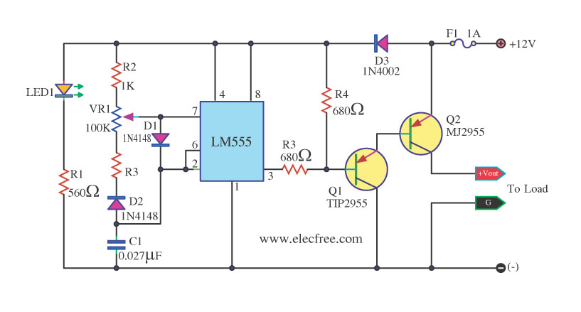
This circuit is a DC dimmer circuit that utilizes the LM555 integrated circuit configured as an astable multivibrator. It is capable of adjusting the duty cycle by fine-tuning variable resistors VR1 and VR2. The DC dimmer circuit employs the LM555...
This circuit uses the effect of a FET as the power to act through the gate with the source to connect. The voltage may vary between 4V and 30V, the current through the LED should constantly be around 15mA....
Many TOPSwitch TOP223 flyback power supply applications require two or more outputs to supply a variety of secondary circuits. Typical consumer applications of these multiple output converters include televisions and related products such as set-top decoders and video cassette...
Dual Channel Relay Board is a simple and convenient way to interface 2 relays for switching application in your project. Input - 12 VDC @ 84 mA. Output - two SPDT relay. Relay specification - 5 A @ 230...
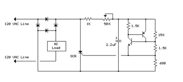
The full wave phase control circuit below was found in an RCA power circuits book from 1969. The load is placed in series with the AC line and the four diodes. The full wave phase control circuit is designed to...