
120V AC Lamp Dimmer

The full wave phase control circuit is designed to regulate the power delivered to a load by controlling the phase angle of the AC waveform. This circuit typically consists of four diodes arranged in a bridge configuration, allowing for the conversion of AC to DC while enabling control over the effective voltage applied to the load.
In this configuration, the load is connected in series with the AC line. When the AC voltage is applied, the diodes conduct current during both the positive and negative halves of the AC cycle, effectively allowing the load to receive power during both phases. The phase control is achieved by delaying the conduction angle of the diodes, which is done using a control circuit, often involving a triac or a similar device.
The control circuit determines the point in each half-cycle when the diodes will start conducting, thereby controlling the average power delivered to the load. This method is commonly utilized in applications such as light dimmers, motor speed controllers, and heating elements, where precise control over the power is necessary.
Key components of the circuit may include:
- Diodes: Four diodes configured in a bridge rectifier arrangement, which allows for full-wave rectification of the AC input.
- Control device: A triac or similar semiconductor device that can be triggered to control the phase angle.
- Load: The device or component that requires power, which is connected in series with the AC line.
The overall performance of the circuit can be influenced by several factors, including the characteristics of the load, the control method employed, and the design of the control circuit. Proper heat dissipation mechanisms may also be necessary to ensure reliable operation, particularly in high-power applications.The full wave phase control circuit below was found in a RCA power circuits book from 1969. The load is placed in series with the AC line and the four dio.. 🔗 External reference
Related Circuits
This circuit is designed to convert continuously lit lamps into flashing lights. It can be easily integrated into an existing circuit by inserting it between the lamp and the negative supply. It is particularly suitable for use with car...
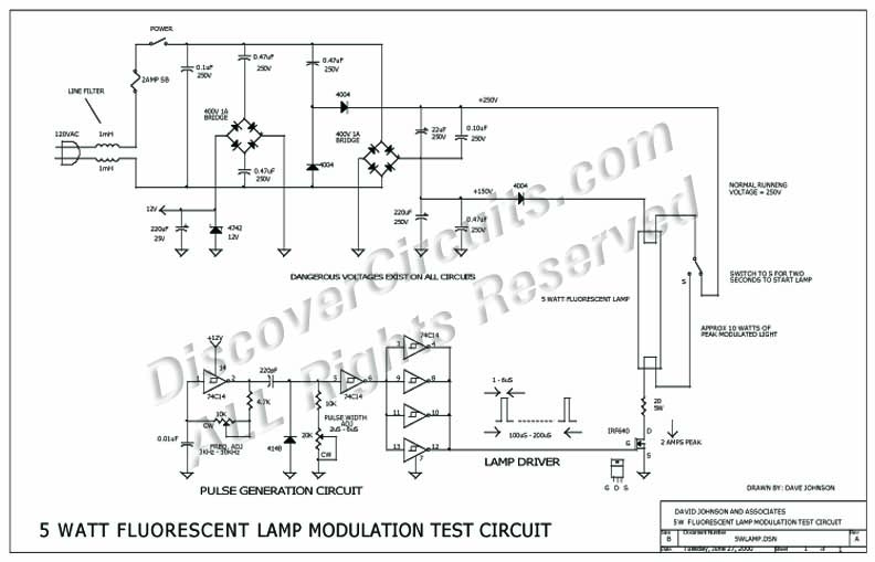
The circuit was designed to experiment with using small fluorescent lamps as a broad pattern source of modulated light. The circuit delivers narrow 1 μs pulses to the small lamp at a frequency of 10 kHz. Each pulse generates...
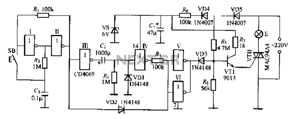
A delay lamp circuit is ideal for bedside tables, featuring a button (SB) that turns the light on and off. If the button is not pressed, the circuit maintains a delay before the light turns off. If the light...
Capacitors C1 and C2, in conjunction with a speed controller, function by receiving voltage at the gate of the MOSFET. When the voltage on C is applied, it activates the operation of the MOSFET. In this circuit configuration, capacitors C1...
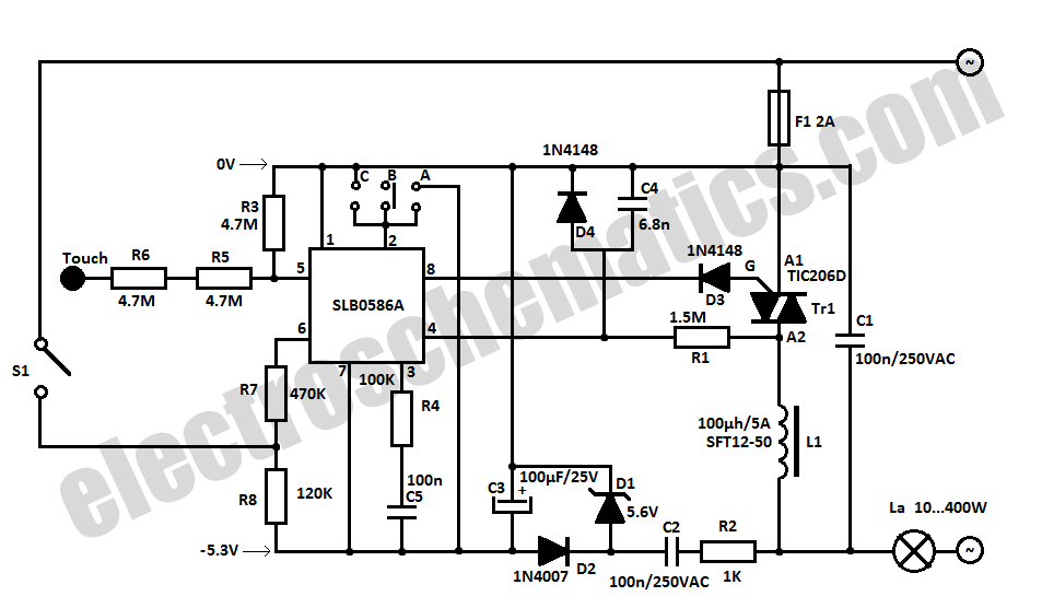
The SLB0586A integrated circuit from Siemens can be utilized to create a simple touch light dimmer circuit, allowing for the adjustment of lamp intensity. When paired with a TIC206D triac, this setup enables smooth regulation of light intensity for...
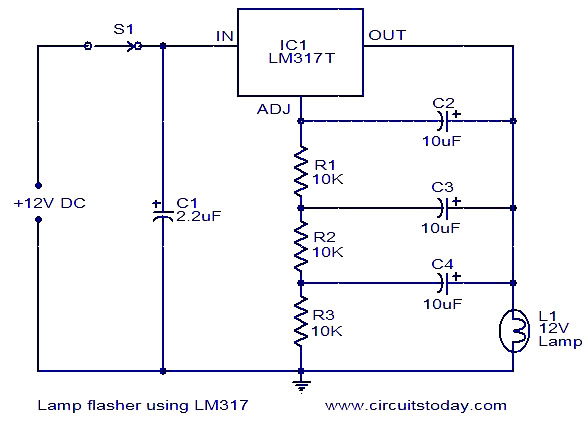
This document describes a lamp flasher circuit utilizing the adjustable voltage regulator IC LM317T. The LM317 can supply a maximum current of 1A, making it suitable for use with lamps up to 12W. This type of circuit has significant...