
Triangle- And Square-Wave Generator Circuit

The described circuit is designed to produce high-precision triangle and square waveforms, which are widely used in various electronic applications, including signal processing, waveform generation, and testing. The circuit operates by employing an operational amplifier (op-amp) configured to generate these waveforms, leveraging the properties of feedback and resistor ratios to control amplitude and frequency.
The square wave output is defined by the op-amp A1's output swing, which is influenced by the power supply voltage and the characteristics of the op-amp itself. The amplitude of the triangle wave is established by the feedback network formed by resistors R1 and R2. The relationship between these resistors determines the peak-to-peak voltage of the triangle waveform, allowing for precise control over the output characteristics.
The oscillation frequency, given by the formula 1/(0.69 ft C), indicates that the frequency is inversely proportional to the product of the feedback capacitor (C) and a time constant factor (t). This relationship is critical for applications requiring specific frequency outputs, such as modulation and timing circuits. The circuit's ability to maintain a 50% duty cycle for the square wave output is particularly beneficial in digital applications, ensuring that the waveform remains symmetrical, which is essential for accurate timing and signal integrity.
The choice of a fast op-amp is crucial for the circuit's performance, as it directly affects the rise and fall times of the square wave output. Fast op-amps can handle higher frequencies without significant distortion, thus ensuring that the output waveforms are clean and well-defined. The open-loop operation of the amplifier simplifies the design by eliminating the need for additional compensation, streamlining the circuit while maintaining performance.
For the triangle wave generation, a compensated op-amp is recommended to ensure stability and linearity in the output waveform. The MC1458 dual op-amp is an excellent choice for this application, providing flexibility to implement both the triangle and square wave generation within a single package. This integration reduces board space and component count, making the design more efficient.
In summary, this circuit provides a robust solution for generating precision triangle and square waves, with adjustable amplitude and frequency characteristics suitable for various electronic applications. The use of high-performance op-amps and careful design considerations ensures reliable operation and high-quality waveform generation. The circuit will generate precision triangle and square waves. The output amplitude of the square wave is set by the output swing of op amp Al, xndRl/R2 sets the triangle amplitude. The frequency of oscillation in either case is approximately l/0.69ftC. The square wave will maintain 50% duty cycleeven if the amplitude of the oscillation is not symmetrical.
The use of a fast op amp in this circuit will allow good square waves to be generated to quite liigh frequencies. Because the amplifier runs open-loop, compensation is not necessary. The triangle- generating amplifier should be a compensated type. A dual op amp, such as the MCI458, can be used for most applications.
Related Circuits
The two circuits below illustrate the application of the 555 timer to activate a relay for a specified duration by pressing a momentary normally open (N/O) push button. The circuit on the left can be used for longer time...
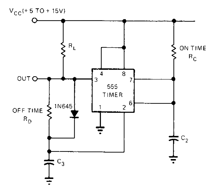
The 555 timer circuit has unsteady open and closing times that are independent of one another. One time constant is given by 1.1RcC2, while another time constant is defined as 1.1RcC3. The free-running period is the sum of these...
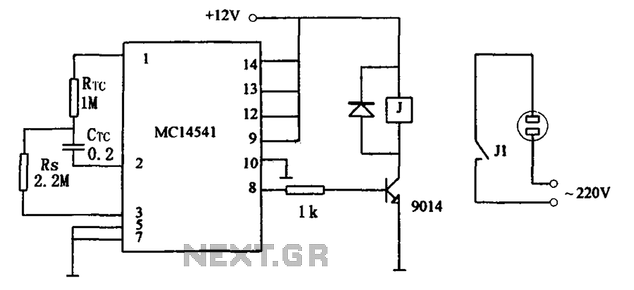
The circuit illustrated in FIG MC14541 is a straightforward timing circuit utilizing the MC14541 integrated circuit (IC). By adjusting the parameter map, the timing can be set for a duration of 3 hours, with options to select various RTC,...
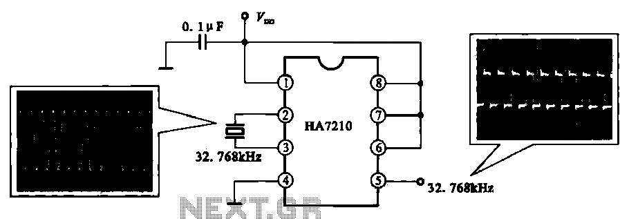
This circuit illustrates a 32.768 kHz micro-power clock oscillator, suitable for use in mobile phones, laptop computers, and home appliances. It generates a clock signal that can be utilized in various applications. The 32.768 kHz micro-power clock oscillator circuit is...
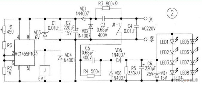
The circuit is depicted in Figure 1, while the electrical schematic diagram is presented in Figure 2. The AC voltage of 220V is reduced by components C3 and R3. The diodes VD1 and VD2 rectify the voltage, and capacitors...
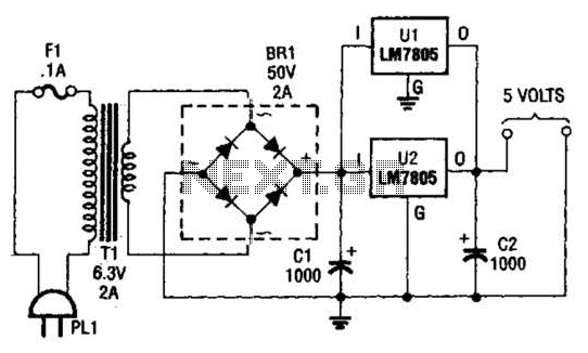
This DC supply is excellent for operating battery-powered antique radios, as it is designed to prevent damage to the tube filaments. The circuit is useful for powering the filaments of 00-A, 01-A, 112A, and 71A tubes, which require 5V...