
Triangle Waveform Signal Generator
This circuit employs an operational amplifier (op-amp) configured in an integrator setup to produce a triangle waveform. The input signal is typically a square waveform, which the op-amp integrates to generate the desired triangular output. The frequency and amplitude of the triangle waveform depend on the characteristics of the input signal and the feedback components used in the circuit.
Key components of the circuit include resistors and capacitors that determine the time constants for charging and discharging, thus influencing the slope of the triangle waveform. The feedback resistor and capacitor values are critical; they must be selected carefully to achieve the desired frequency response and output amplitude. Additionally, the op-amp should be chosen based on its bandwidth and slew rate to ensure that it can handle the frequency of operation without distortion.
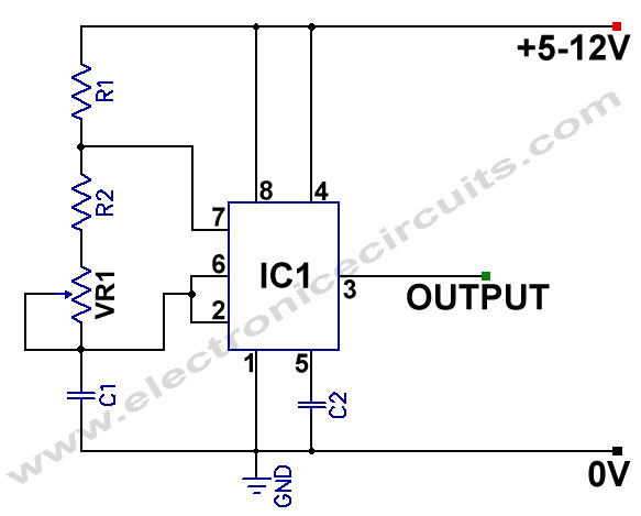
The circuit may also include diodes for clamping the output to prevent it from exceeding specified voltage levels, ensuring that the waveform remains within the desired range. Proper power supply decoupling is essential to maintain stability and reduce noise in the output signal. Overall, this configuration provides a reliable method for generating a symmetrical triangle waveform suitable for various applications in signal processing and waveform generation.A symmetrical, mV peak to peak triangle waveform can be generated by the circuit depicted in the following schematic diagram. This circuit is featured with.. 🔗 External reference
Related Circuits

The microcontroller design features the microcontroller (MCU) in hibernation mode, which can only be awakened by a pulse (high-low-high) signal on the reset pin (active low). An accelerometer or an external real-time clock (RTC) serves as the wake-up source....
555 Variable Frequency Square Wave Generator. This simple 555 Variable Frequency Square Wave Generator produces a variable frequency output. The 555 Variable Frequency Square Wave Generator is a versatile circuit that utilizes the 555 timer IC to generate square wave...
Square wave generators are typically based on symmetrical multivibrators using bipolar transistors of the same structure, along with two frequency-determining networks. However, a simpler oscillator can be constructed with two transistors of different structures (refer to figure 1) utilizing...

Generating sine waves with controlled frequencies over a wide range is challenging when using RC or LC sinusoidal oscillators. However, this can be effectively achieved using a wideband digital square wave oscillator, a counter, and a weighted summing network....
This is a simple function generator built around a single 8038 waveform generator IC. The circuit is capable of producing sine, square, or triangle waves within a frequency range of 20Hz to 200kHz. The function generator circuit utilizes the 8038...
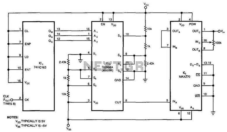
This circuit generates a pure sine wave with a total harmonic distortion (THD) of -80 dB and a frequency equal to the cutoff frequency (fc) of the filter in IC3. It utilizes a counter, an 8-channel analog multiplexer, and...