
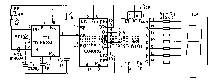
Triple Stroboscope circuit

The circuit utilizes the NE555 timer in astable mode to generate a continuous rectangular pulse output. This output can be used to trigger stroboscopic lights, enabling the visualization of fast-moving objects by producing a series of flashes that illuminate the object at specific intervals. The frequency of the output signal can be adjusted by varying the resistor and capacitor values connected to the NE555 timer, allowing for customization based on the application requirements.
The power supply section of the circuit is designed to provide a stable voltage to the NE555 timer and associated components. The transformer (TR1) steps down the AC voltage from the mains supply to a lower level suitable for the circuit. The rectifier bridge converts the AC voltage to DC, while the zener diode is employed for voltage regulation, ensuring that the NE555 timer receives a consistent voltage, which is critical for reliable operation.
In summary, this circuit provides a practical solution for observing movement using stroboscopic effects, leveraging the NE555 timer's capabilities and a straightforward low-power supply design. Proper selection of components and configurations will enhance the performance and reliability of the circuit in various applications.This circuit enables observation of movement between other stroboscopes. Generation of rectangular signal is based on NE555. This circuit requires a low power supply that is made from a simple transformer TR1, traditional rectifier bridge and zener diode.. 🔗 External reference
Related Circuits
Digital timers feature a clear and precise display. They represent time intervals based on pulse signals, which are decoded by a digital device with a digital display unit. The circuit described pertains to a digital display for these timers,...
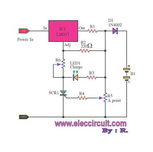
When building a lead-acid battery charger for a 6V or 12V battery, there are various methods available. One preferred option is the use of the IC LM317. The LM317 is a versatile adjustable voltage regulator that can be effectively utilized...

The AD654 voltage-frequency converter is a low-cost device that operates with a single supply voltage ranging from +5V to +36V, as well as with dual supplies of +5V to +18V. It can handle a maximum input voltage of 36V...
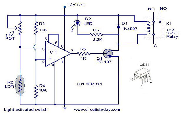
The following circuit illustrates a Light Activated Switch Circuit Diagram. This circuit is based on the LM311 integrated circuit, which functions as a voltage comparator. The Light Activated Switch Circuit utilizes the LM311 voltage comparator to control the switching of...
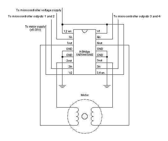
A stepper motor is a motor controlled by a series of electromagnetic coils. The center shaft has a series of magnets mounted on it, and the coils surrounding the shaft are alternately energized or de-energized, creating magnetic fields that...

An innovative current detection method eliminates the power loss associated with the sense resistor in series with the motor. A 4-digit analog converter (DAC) facilitates digital control of the motor current path, simplifying the implementation of full, half, and...