
Tuch Sensitive Light Dimmer Circuit

The SLB0586A touch light dimmer circuit is designed to provide user-friendly control over lighting conditions through a touch-sensitive interface. The integration of the TIC206D triac allows for effective management of AC loads, ensuring that the circuit can handle the specified power range efficiently. The 100 µH coil serves a critical role in minimizing electromagnetic interference generated during switching events, thereby enhancing the overall performance and reliability of the circuit.
The circuit operates on a low-voltage supply derived from the resistive and capacitive components (R2, C2) and the diode (D1) which rectifies the voltage to a stable level. This regulated voltage is essential for the operation of the SLB0586A, ensuring that it functions correctly even with fluctuations in the main supply.
The touch sensor interface, connected through high-value resistors R5 and R6, ensures that the circuit remains safe for user interaction by limiting the current that can flow through the touch sensor. This design consideration is crucial for preventing accidental shocks and ensuring compliance with safety standards.
The three connection modes (A, B, C) provide versatility in operation. Mode B allows for a convenient "last setting recall" feature, which is particularly useful in residential applications where users may prefer to return to their last preferred light level. In contrast, modes A and C facilitate a more straightforward dimming experience, starting from a low intensity, which can be beneficial in scenarios where a gradual increase in brightness is desirable.
The touch control mechanism is responsive, with the short touch function enabling quick ON/OFF control, while the long touch initiates a dimming sequence, allowing users to easily set their preferred lighting level. This intuitive interaction model enhances user experience, making the circuit suitable for a variety of applications, including home lighting, mood lighting, and decorative installations.With IC SLB0586A from Siemens you can build a simple touch light dimmer circuit that will allow you to adjust the lamp intensity. Together with a TIC206D triac, it enables smooth regulation of light intensity from a bulb of 10W 400W.
A coil of 100 µH/5A is required to suppress switching noise. more The voltage supply is obtained through R2, C2 , D1 and C3 and is about 5. 3V below the network potential. The touch sensor that is used to drive the IC is connected at pin 5 through two 4. 7M © resistors, R5 and R6, in order to ensure user security. In the adjustable touch lamp schematic we can see three selection connection, for selecting one of three modes of the IC. When the B connection is used, the light will always be ON at the last level that we used. With A or C connection the light will be ON at the minimum intensity. With B or C, the purpose of regulation is reversed with each use. When the sensor is touched for a short period of time (50 400 ms), the lamp will be ON or OFF. If the sensor is touched for a longer period of time it will start the regulation process. 🔗 External reference
Related Circuits
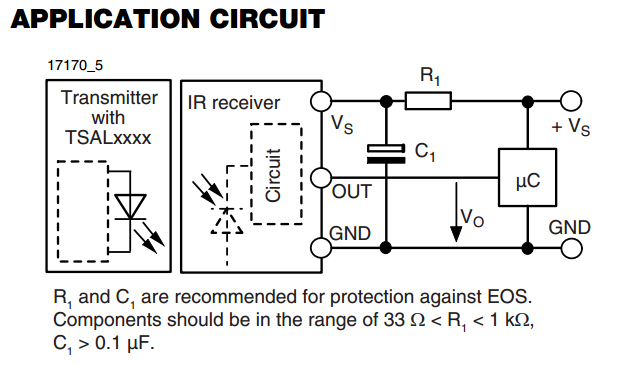
There is an interest in starting an introductory electronics project using an infrared (IR) sensor, but there is some confusion regarding the application circuit provided in the datasheet. The recommended resistor value is significantly lower than the calculated value....
A dimmer is not commonly found in a caravan or on a boat. This document outlines how to create one. If the goal is to adjust the ambiance while entertaining friends and acquaintances, this circuit allows for that capability....
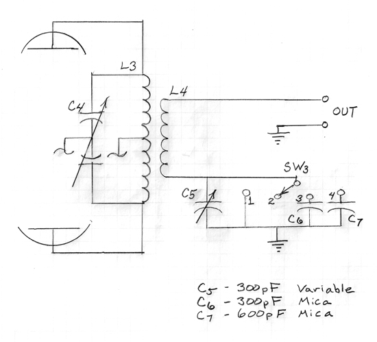
A series capacitor is most effective for low impedance loads, while a parallel capacitor is utilized for high impedance loads. The current standard is a 50-ohm antenna and coax system that requires a series capacitor for loading adjustment. With...
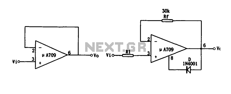
Figure (a) illustrates a voltage follower circuit, which serves as a specific instance of an in-phase amplifying circuit. The input signal originates from an integrated operational amplifier. At the conclusion of the introduction phase, the feedback resistor is set...
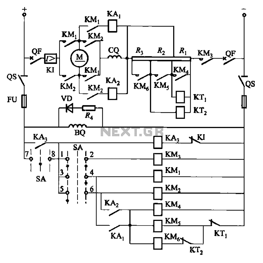
The circuit depicted in Figure 3-201 includes two starting resistors, with one controlled by a time relay. A master switch (SA) is utilized to manage the motor's reversing operation. The circuit incorporates a reverse braking mechanism, which is automatically...

The circuit operation principle of the device illustrated in the figure is as follows: When the barbed wire is intact, the output pin of the LSE is high due to the absence of contact. Consequently, the transistor VT is...