
Understanding circuit diagram on datasheet and resistor value

In the context of electronics, the application circuit for an infrared (IR) sensor typically involves a few key components: the IR sensor itself, a resistor, and potentially a capacitor for decoupling. The resistor is crucial for limiting the current flowing through the sensor. The datasheet's recommended resistor values, which range from 33 Ω to 1 kΩ, may seem low compared to the calculated requirement of 10 kΩ when operating at 0.35 mA with a 3.3V supply. This discrepancy can arise from different operational modes of the sensor, such as its sensitivity and the specific application requirements. The low resistor values could be intended for specific configurations or to ensure that the sensor operates within its optimal range under varying conditions.
When considering the decoupling capacitor, it serves to stabilize the voltage supply by providing transient current during sudden increases in demand, which is common in digital circuits. Even in low current applications, such as one operating at 0.35 mA, including a decoupling capacitor can be beneficial. It helps to mitigate voltage fluctuations that may occur during operation, especially when the sensor is activated or when other components in the circuit draw current intermittently. Given that the absolute maximum current specified is 3 mA, it is advisable to include the capacitor to ensure reliable operation, as it can help manage unexpected current spikes and maintain stable circuit performance. The value of the capacitor can be determined based on the specific requirements of the circuit and the frequency of operation but typically ranges from a few microfarads to several microfarads.
In summary, careful consideration of the resistor values and the inclusion of a decoupling capacitor is essential for the reliable operation of the IR sensor circuit. Understanding the specifications provided in the datasheet and their implications on circuit performance is key to successfully implementing the project.Interested in starting an intro electronics project using a IR sensor and am having a little trouble understand the application circuit given on the datasheet of the circuit. The value of resistor they recommend using is far less then the one I calculate I should need. The supply current given on the datasheet is 0. 27mA - 0. 45mA and the suppl y voltage is 2. 5V - 5. 5V. I intend to run this sensor at 0. 35mA with 3. 3V and this yields a needed resistance of around 10K ohms; far greater than the 33 - 1K ohms suggested. As this is my first venture into electronics, could someone help me to understand how using such a low resistor as specified would work when the math says otherwise On a slightly related note, from what I understand, the capacitor in the circuit is called a decoupling capacitor and is used to provide the extra current during short periods of high current draw so the voltage supply does not.
Because this is such a low current circuit (or is 0. 35mA low ), is it fine if I leave the capacitor out or should I include it because the datasheet lists the absolute maximum current as 3mA and the circuit may try to draw that much 🔗 External reference
Related Circuits
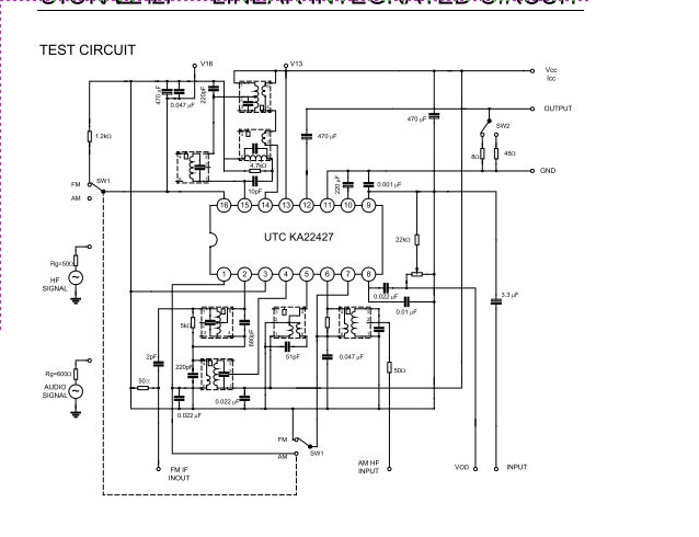
The UTC KA22427 is a single-chip AM/FM radio integrated circuit designed for portable radio applications. It features an AM amplifier, local oscillator, AM mixer, AM/FM amplifier, AM AGC, and FM AGC circuitry. The UTC KA22427 integrated circuit is engineered to...
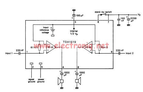
The TDA1519 circuit can deliver 2x6 watts output power. TDA1519 is an integrated class-B dual output amplifier in a 9-lead single in-line (SIL) plastic medium power package primarily developed for car radio applications. The TDA1519 is a robust integrated circuit...
This compact circuit enables automatic recording of phone conversations. It connects to the phone line, the microphone input of a tape recorder, and the remote control jack of the recorder. The circuit detects the voltage level in the phone...
This circuit is an enhanced Hartley oscillator, which allows for frequency adjustment within a specified range by altering the base current. The output signal amplitude exceeds 6V when tested with a 6kΩ load resistance, making it suitable for use...
The circuits in Figure 1 and Figure 2 demonstrate specific advantages over the circuit presented in the Design Idea in EDN, titled "Circuit detects first event," published on May 3, 2001, page 89. The n-player first-event detection circuit provides...
Colour TV Camera Tutorial - Block Diagrams - Electronics Circuit and Tutorials - Hobby Science Projects - Modulation allows low-frequency audio signals to be transmitted over long distances. This is achieved by superimposing the low-frequency audio signal onto a...