
Tuned Rf Wavemeter

The circuit utilizes two inductors, L1 and L2, configured as a tuned transformer. The design aims for an optimal turns ratio of approximately 1:3, which facilitates effective energy transfer between the two inductors while allowing for impedance matching to the load. The tuning element, C1, is critical in determining the operational frequency of the circuit.
The frequency range supported by this configuration spans from 10 kHz to over 200 MHz. This wide range is achievable by adjusting the capacitance value of C1. For HF applications, a variable capacitor with a capacitance of 140 pF is appropriate, allowing fine-tuning of the circuit to achieve resonance at lower frequencies. In contrast, for VHF applications, a lower capacitance value of around 25 pF is recommended to accommodate the higher frequency range.
In addition to the tuned transformer configuration, the use of a 2.5 RF choke introduces an alternative functionality. This component can create an untuned wavemeter setup, which may be beneficial for specific applications where frequency measurement or monitoring is required without the need for precise tuning. The RF choke serves to block certain frequencies while allowing others to pass, thus providing a means to analyze the frequency response of the circuit.
Overall, this circuit design offers versatility in tuning and frequency management, making it suitable for a variety of RF applications. The careful selection of inductance and capacitance values is essential in achieving the desired performance characteristics. Ll and L2 form a tuned transformer. About a 1:3 turns ratio is optimum. L2 and CI tune to the desired frequency. The fre quency range can be 10 kHz to over 200 MHz, depending on the value of CI. For HF use, CI can be a 140-pF variable. For VHF, use about 25 pF. Use of a 2.5 RF choke will yield an untuned wavemeter.
Related Circuits
Millimeter-wave frequency bands are appealing due to their wide available bandwidths. Signals can be generated in various ways; however, for each type of oscillator, electronic tuning of the source in a defined and controlled manner is desirable. Employing a...
This application note presents alternate RF matching networks for the MAX2653 SiGe LNA, tuned for the GPS band (1575 MHz center frequency). Performance metrics (supply current, forward gain, noise figure, IIP3, reverse isolation, and input/output return loss) for both...
This application note presents the component values and measured performance for the MAX2681 mixer IC when tuned for GPS operation at 1575 MHz. The MAX2681 is a high-performance mixer integrated circuit designed for use in GPS applications, particularly at the...
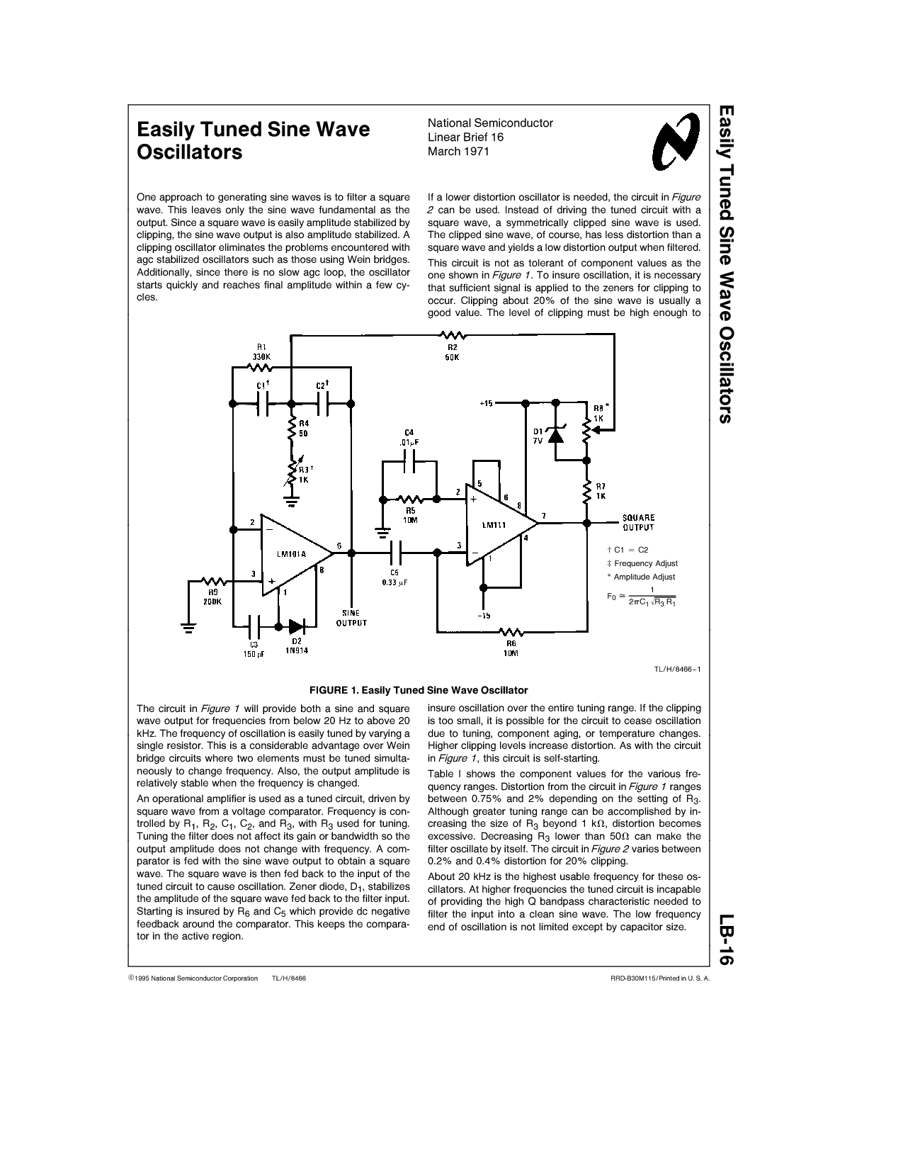
One approach to generating sine waves is to filter a square wave. This leaves only the sine wave fundamental as the output. If a lower distortion oscillator is needed, the circuit in Figure 2 can be used. Instead of...
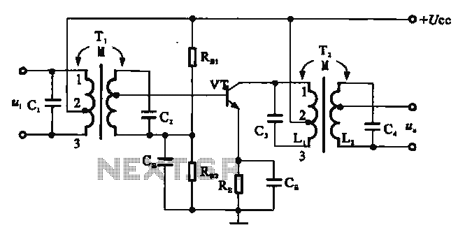
There are two resonant circuits in a double-tuned amplifier circuit, which consists of transformers T1 and T2 with primary and secondary coils that include parallel resonance capacitors. This circuit exhibits a resonance function and can be classified based on...
Superheterodyne receivers have been mass-produced since around 1924, but for reasons of cost did not become successful until the 1930s. Superheterodyne receivers represent a pivotal advancement in radio technology, characterized by their ability to convert high-frequency signals into lower...