
Tunnel Diode Oscillator

Tunnel diodes, also known as Esaki diodes, are semiconductor devices that exploit the quantum mechanical phenomenon of tunneling to achieve their operation. Unlike conventional diodes, which rely on the rectification of current through a p-n junction, tunnel diodes have a heavily doped p-n junction that allows for the tunneling of charge carriers. This unique structure enables the diode to exhibit negative resistance in certain regions of its current-voltage (I-V) characteristics.
When a small forward voltage is applied to a tunnel diode, electrons from the valence band of the p-type material can tunnel through the narrow energy barrier to the conduction band of the n-type material. This tunneling effect results in a small forward current, which is significantly higher than what would be expected from conventional diodes under similar conditions. The I-V curve of a tunnel diode typically shows an initial increase in current with voltage, followed by a region where the current decreases with increasing voltage—a phenomenon referred to as negative resistance.
Tunnel diodes are characterized by their high speed and ability to operate at microwave frequencies, making them suitable for various applications such as oscillators, amplifiers, and high-frequency switching circuits. The precise control of the doping levels and the thickness of the junction can be critical in optimizing the performance of the device, allowing for tailored responses in specific electronic applications. The understanding of quantum mechanical tunneling and its implications in semiconductor physics is essential for the effective design and implementation of tunnel diode circuits.The excess small forward current flow in a tunnel or Esaki diode is a manifestation of quantum mechanical tunneling. 🔗 External reference
Related Circuits
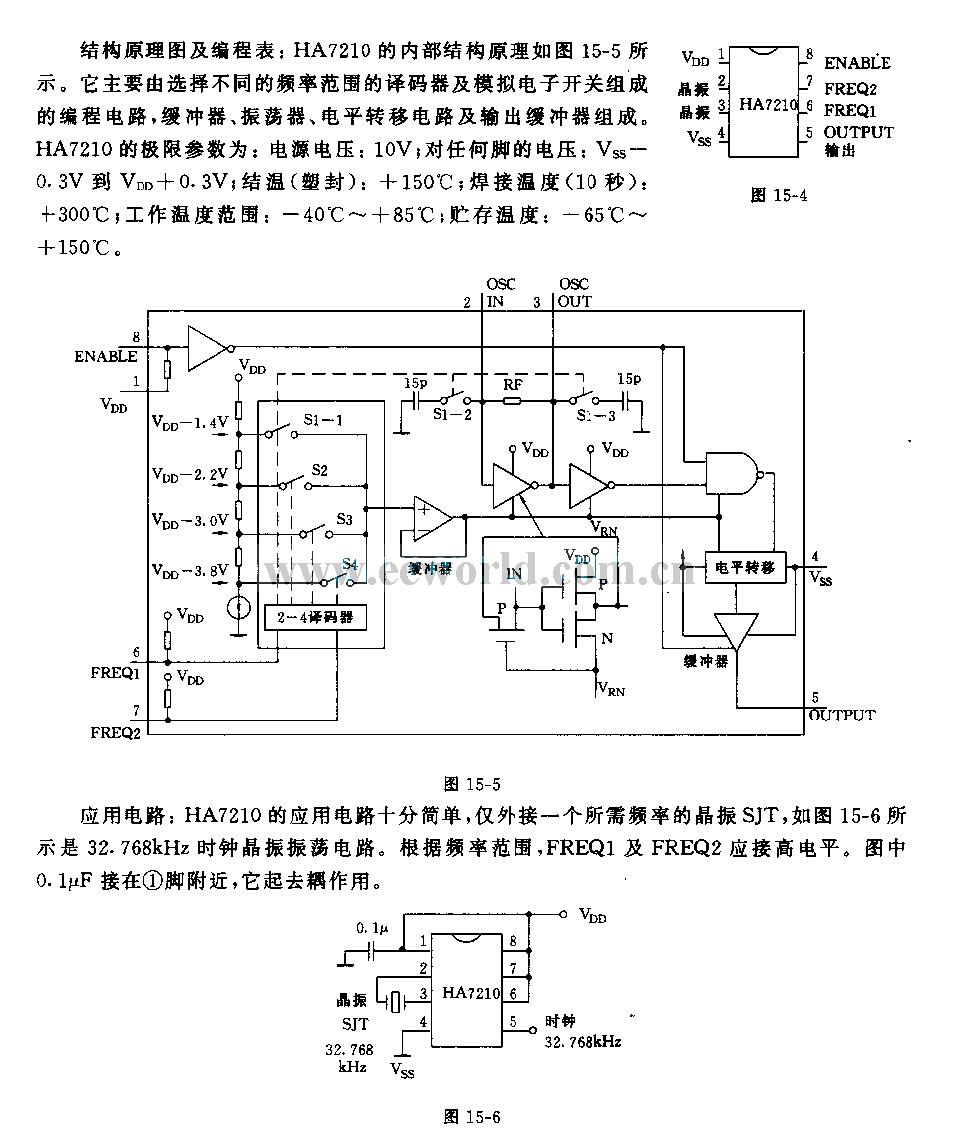
Features: 1. The operating voltage is low, functioning with a single supply of 2.0V. 2. Power consumption is minimal, with a supply current of 5 µA at 32 kHz and 130 µA at 1 MHz. 3. It has a...
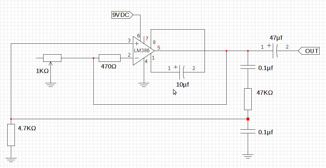
The design utilizes the LM386n-1 integrated circuit, powered by a single power supply to maintain a compact layout. There is a need to control the frequency, and the user is inquiring about which component values should be adjusted for...
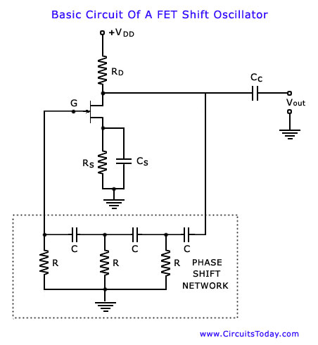
The phase shift oscillator is selected as an initial example as it clearly illustrates the principles discussed in the previous blog post. The circuit diagram emphasizes the amplifier and feedback network. It consists of a common source FET amplifier...
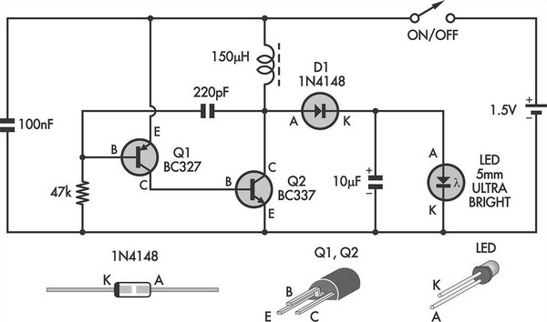
This simple LED torch is driven by a 2-transistor blocking oscillator that steps up the voltage from a 1.5V cell. It relies on the inherent current limiting of the 150 µH choke to protect the white LED from overdrive....
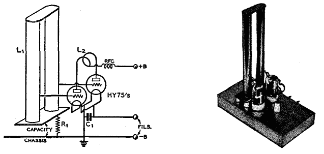
The use of a quarter-wave parallel-wire line as a tuning unit has been discussed in the chapter on Short-Lines, where it was pointed out that these circuits have comparatively high Q even at higher frequencies. Their significant length (approximately...

The circuit utilizes a tuned circuit for frequency selection, designed to operate at approximately 51 kHz. The 2N3565 transistor amplifies the output generated by the tuned circuit. The described circuit operates on the principle of resonance, where the tuned circuit...