
tv remote control jammer

The circuit operates by continuously emitting a modulated infrared signal at a frequency of 38 kHz, which is the standard frequency used by many remote control devices. This modulation is essential for effectively confusing the TV's infrared receiver. The IR emitter diode is driven by a transistor that is configured to switch on and off rapidly, creating the necessary modulation. The two 1N4148 diodes are connected in such a way that they limit the current through the IR LED, ensuring that it operates within safe parameters and prolongs its lifespan.
The choice of the resistor value (5.6 ohms) is critical as it helps to set the appropriate current level through the circuit to maintain the desired output without overheating the components. The transistor acts as a switch; when activated, it allows current to flow through the IR LED, emitting the infrared light. The circuit can be powered by a standard DC power supply, with careful attention given to the polarity to prevent damage to the components.
Overall, this circuit serves as an effective tool for creating a localized interference with infrared signals, making it particularly useful in situations where uninterrupted viewing is desired. It is important to note that while this circuit can provide temporary relief from unwanted channel changes, it should be used responsibly and ethically, as it interferes with the intended functionality of remote-controlled devices.This circuit confuses the infra-red receiver in a TV. It produces a constant signal that interferes with the signal from a remote control and prevents the TV detecting a channel-change or any other command. This allows you to watch your own program without anyone changing the channel ! The circuit is adjusted to produce a 38kHz signal. The IR dio de is called an Infra-red transmitting Diode or IR emitter diode to distinguish it from a receiving diode, called an IR receiver or IR receiving diode. (A Photo diode is a receiving diode). There are so many IR emitters that we cannot put a generic number on the circuit to represent the type of diode.
Some types include: CY85G, LD271, CQY37N (45 ), INF3850, INF3880, INF3940 (30 ). The current through the IR LED is limited to 100mA by the inclusion of the two 1N4148 diodes, as these form a constant-current arrangement when combined with the transistor and 5R6 resistor. 🔗 External reference
Related Circuits
A photodiode, SFH2030, serves as an infrared sensor. A MOSFET operational amplifier, CA3140, is utilized in differential mode to amplify the current pulses from the photodiode. LED1, an ordinary colored LED, illuminates when infrared radiation is detected. The output...
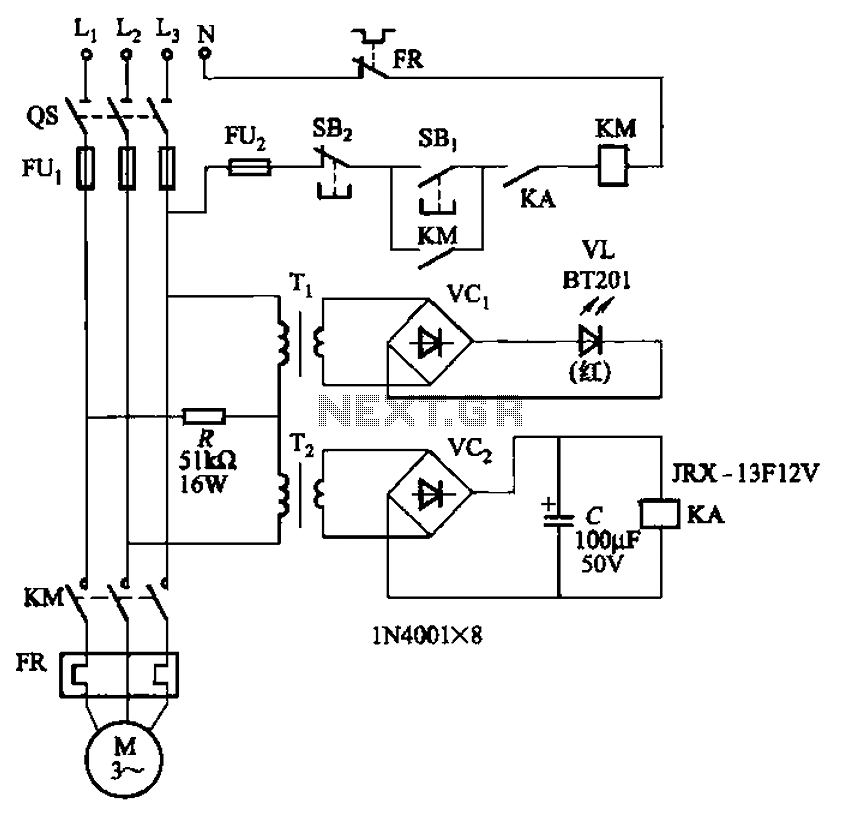
The circuit depicted in Figure 3-92 employs a dual-phase sequence protection relay for sensing. When the power supply exhibits a positive phase sequence (U, V, W), the relay KA is activated. If the power supply maintains the correct phase...
The VNGBOX microcontroller must generate a precise, high-resolution, and low-noise DC control voltage to accurately steer the reference oscillator phase. Any noise on this signal can introduce noise to the reference, and any non-linearity, particularly unexpected steps in the...
Even though the power was off, there was AC present at the handle plug, and a short circuit occurred. Upon disassembly, a blown transistor was discovered. An attempt was made to fix the issue, but after one month and...
Rsense will cause Q2 to conduct when a threshold of approximately 0.65V is reached. Rbias will determine the extent of this limitation, although this aspect remains unclear. Particularly, if Rsense is positioned on the high side, simply activating Q2...
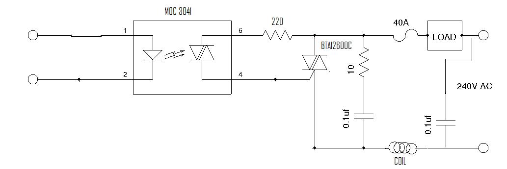
This circuit controls resistive and inductive loads up to 2,500W. Its primary component is the Siemens TLE3103 integrated phase control circuit, which includes its own power supply, a zero voltage crossing detector, and a logic driver. An additional feature...