
40 meter Direct Conversion Receiver

The 40-meter direct conversion receiver is designed to facilitate the reception of amateur radio communications, specifically in the 7 MHz frequency range, which is popular for both CW (Continuous Wave) and SSB (Single Sideband) modes. This receiver operates by converting the incoming RF (radio frequency) signals directly to audio frequencies, allowing for easier processing and listening.
The circuit typically consists of a few key components: an RF amplifier, a mixer, a local oscillator, and an audio amplifier. The RF amplifier boosts the weak signals received by the antenna, ensuring that they are strong enough for further processing. The mixer then combines the amplified RF signal with a signal from the local oscillator, which is tuned to the desired frequency. This mixing process produces an intermediate frequency (IF) that is lower than the original RF signal, making it easier to filter and amplify.
In CW mode, the receiver can demodulate the on-off keying of the signal, while in SSB mode, it can extract the audio information from the modulated carrier wave. The audio output can be connected to headphones or a speaker for listening. Additional features may include adjustable filters to improve selectivity and reduce interference from adjacent frequencies, as well as volume controls for the audio output.
This direct conversion method is favored for its simplicity and effectiveness, making it a popular choice among amateur radio enthusiasts for building their own receivers. The design can be further enhanced with additional components such as automatic gain control (AGC) to maintain consistent audio levels and improved sensitivity, contributing to an overall better reception experience.40 meter Direct Conversion Receiver. Using the circuit of 40-metre band direct-conversion receiver descr- ibed here, one can listen to amateur radio QSO signals in CW as well as in SSB mode in. 🔗 External reference
Related Circuits
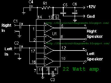
The function of the sound level display circuit is to enhance the appearance of an amplifier circuit or a radio player. It provides an impressive visual representation of audio levels. The sound level display circuit serves as a visual indicator...
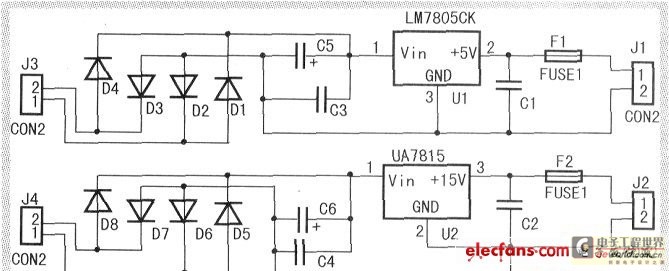
When the input voltage is between 198-242V, the average load current should be maintained at 0.5-1A, and the output voltage must remain at 15V with an error margin of less than 5%. The design and measurement of the stabilized...
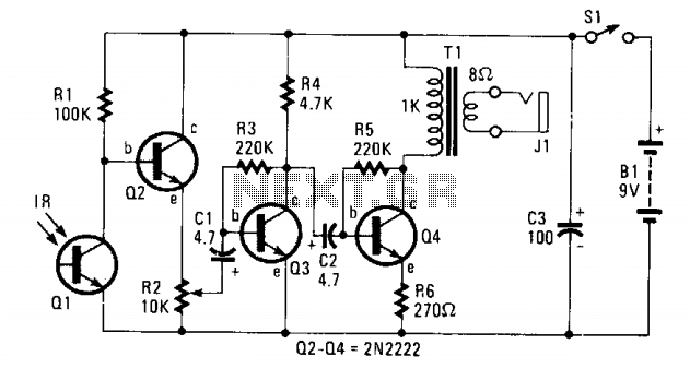
The circuit consists of Q1, a phototransistor that responds to an intensity of amplitude-modulated infrared light source, and a three-stage, high-gain audio amplifier. Transformer T1 is utilized to match the output impedance of the receiver to modern low-impedance (low-Z)...

The basic concept involves a transmitter that emits beeps while the user adjusts a directional antenna to determine the maximum signal strength, indicating the direction of the transmitter. The effectiveness of this method is limited due to the antenna's...
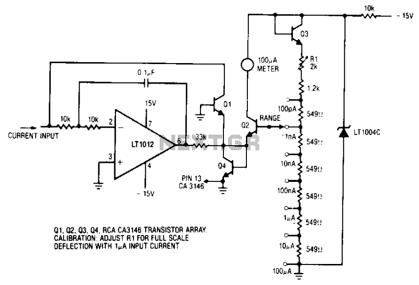
The ammeter measures currents from 100 pA to 100 µA without the use of expensive high-value resistors. Accuracy at 100 µA is limited by the offset voltage between Q1 and Q2, and at 100 pA, it is limited by...
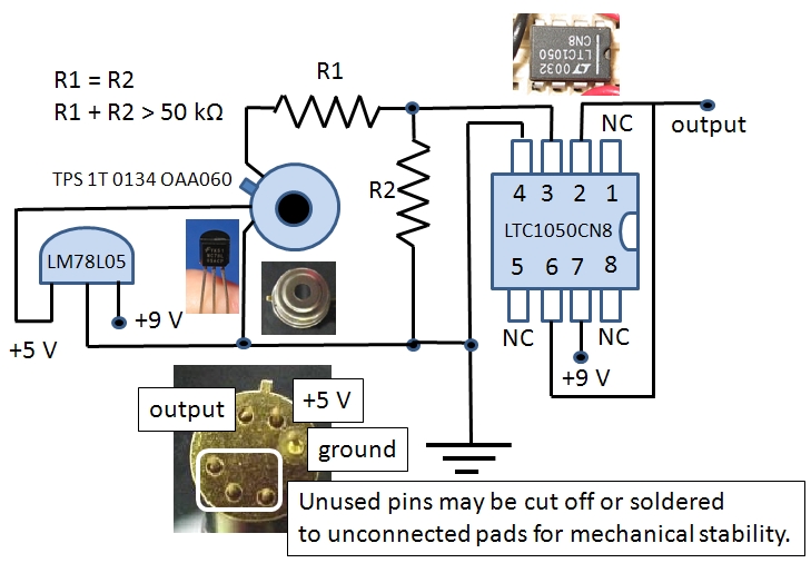
The Excelitas TPS 1T 0134 OAA060 thermopile sensor is a self-contained module that includes a built-in operational amplifier. The designation A2TPMI 334 OAA 60 is used in this document due to its previous identification under the PerkinElmer part number...