
Two-Position Dimmer

The described dimmer circuit operates using a straightforward configuration that includes a switch (S1), another switch (S2), a capacitor, and a resistor. The functionality hinges on the interaction between these components. When S1 is closed, it allows the full supply voltage to reach the load, which is typically a lamp, enabling it to illuminate at full intensity. The role of S2 becomes significant when S1 is open. In this state, closing S2 connects the capacitor in parallel with the load, effectively reducing the voltage across the lamp and thereby dimming it.
The capacitor serves as a critical component that influences the dimming effect. By selecting a capacitor value between 2 µF and 6 µF, the desired dimming level can be achieved based on the lamp's power rating. The choice of a class X2 capacitor is vital due to its safety rating, which ensures it can handle the potential voltage spikes encountered in AC mains applications without failure.
The resistor included in the circuit is essential for preventing arcing or sparking at the contacts of S2 during operation. This is particularly important because, without this resistor, the abrupt connection of the capacitor could lead to a sudden inrush of current, potentially damaging the switch or causing safety hazards.
It is important to note that this dimmer circuit is specifically designed for resistive loads, such as incandescent lamps. The presence of inductive loads, such as motors or transformers, may lead to erratic behavior due to the phase differences introduced by inductance, which the circuit is not designed to handle. Therefore, careful consideration of the load type is necessary when implementing this dimmer circuit to ensure safe and reliable operation.This super-simple dimmer consists of only two components, and it can easily be built into a mains switch. If you do this, don`t forget torst switch off the associated branch circuit in the fuse box, since the mains voltage is always dangerous!
The circuit does not need much explanation. When S1 is closed, the lamp works at full strength, and t he position of S2 does not matter. When S1 is open and S2 is closed, the capacitor causes a voltage drop, so the lamp is dimmed. The power dissipation of the capacitor is practically zero, so the circuit does not generate any heat. The resistor prevents sparking when S2 is closed while S1 is already closed. The value of the capacitor can be matched to the power of the lamp to be dimmed; it should be between 2 and 6 µF.
Be sure to use a class X2 capacitor. Also, don`t forget that this circuit works only with resistive (non-inductive) loads. Unpredictable things can happen with an inductive load! 🔗 External reference
Related Circuits
This circuit is relatively simple yet valuable, as it offers a high-quality interior light delay feature. The circuit for the interior light delay is designed to control the duration for which the interior lights remain illuminated after a door is...
The circuit below is a simple dimmer circuit. A network consisting of R1, R2, VR1, C2, C3, and Q1 controls the triggering angle of the triac by adjusting the variable resistor VR1. The described dimmer circuit employs a TRIAC (Q1)...
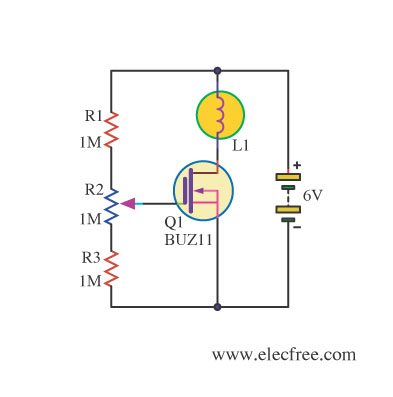
Changing the value of R2 alters the intensity of the lamp in this circuit, demonstrating the utility of a MOSFET as a variable resistor. An N-Channel Power MOSFET, designated as Q1, is utilized in the circuit. The specific part...
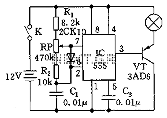
The circuit illustrated in the figure is a dimmer using the 555 timer as the core component. The 555 timer, along with resistors R1, RP, R2, and capacitor C1, forms an astable multivibrator. The oscillation frequency, f, is calculated...
This project presents an effective solution for reducing electricity bills when using high-wattage bulbs. By utilizing miniature components and exercising meticulous care, it is possible to create a low-power lamp dimmer directly within the socket. Instead of employing a...
This circuit utilizes a controlled half-plus fixed half-wave phase control method to regulate an 860-watt lamp load, allowing for power adjustment from half to full capacity. The circuit controls the light output of the lamp, enabling a range from...