
Two Transistors AM Radio Receiver
The described AM radio receiver circuit leverages a minimalist approach by utilizing just two active components, typically a transistor and a diode, to achieve reception in the Medium Wave frequency range. The basic configuration consists of a tuned circuit, which is essential for selecting the desired radio frequency. This tuned circuit can be formed using a combination of inductors and capacitors, which are adjusted to resonate at the frequency of interest.
In this setup, the transistor serves as the amplifying element, providing gain to the weak signals received from the antenna. The diode functions as a demodulator, converting the amplitude-modulated signal into an audio signal that can be further processed or amplified for listening purposes. The circuit design allows for the direct connection of an audio output device, such as a speaker or headphones, to the output of the transistor.
The simplicity of the circuit makes it suitable for educational purposes, demonstrating fundamental principles of radio frequency reception and signal processing. Additionally, this configuration can be adapted for various applications by modifying component values to tune into different frequencies within the MW band, thus allowing for versatility in radio reception. Proper attention must be given to the layout and grounding of the circuit to minimize noise and interference, ensuring optimal performance.Using only two active components, we can build an AM radio receiver working on MW (Medium Wave) Band. The circuit uses straight receiver configuration, where.. 🔗 External reference
Related Circuits
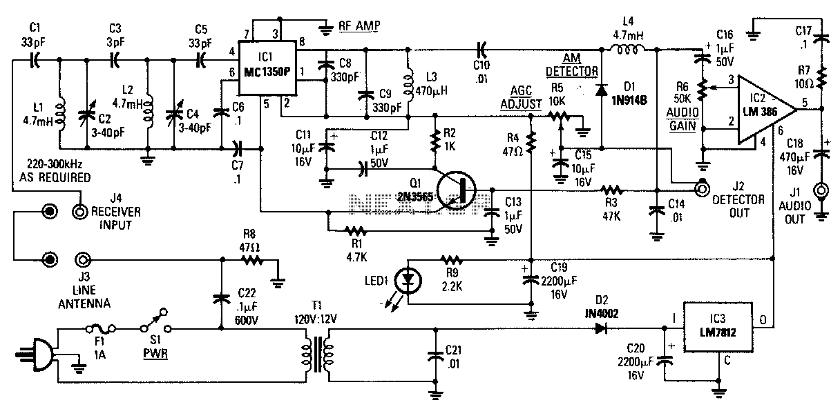
The AM Tuned Radio Frequency (TRF) receiver has a sensitivity of approximately 1 mV at the input for an audio output of 1/2 W. Capacitor C22 couples audio signals from the power line to the PC board and must...
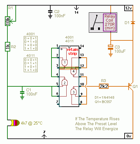
A CMOS 4001 or a CMOS 4011 can be utilized in this circuit, as both contain four two-input gates. The inputs of each gate are connected together, allowing them to function as simple inverters. This means that when both...
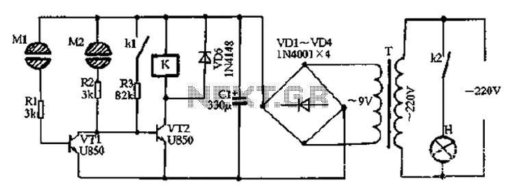
After the power is turned on, 220V AC is stepped down by transformer T. The output is then rectified by the VD1 to VD4 bridge rectifier and filtered by C1 to produce approximately 10V DC voltage for the Darlington...
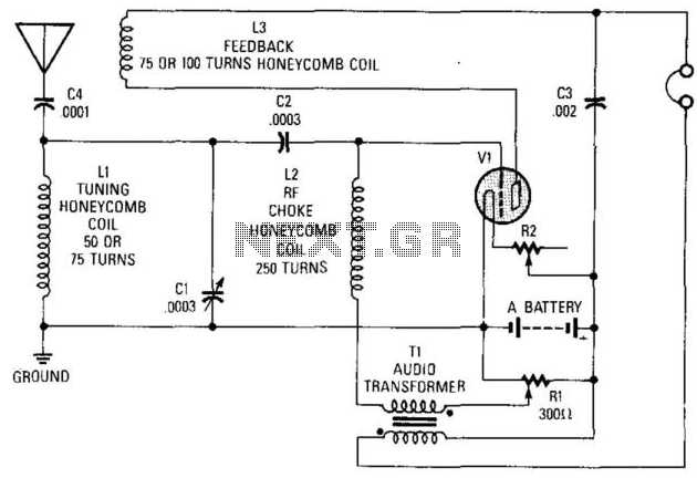
This circuit was utilized in the early days of radio for signal reception. It can employ nearly any battery-operated triode, such as a type 30. The "A" battery provides 3 V, R2 is a 100-ohm rheostat, and the coils...
Cal-(IT)2 is developing several generations of general broad application radio/networking test platforms for wireless research and development. CalRadio I is the first generation. It provides a simple, low-cost platform for 802.11b development from the MAC layer and up. It...
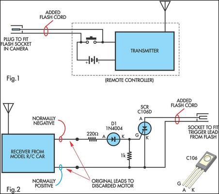
A radio-controlled electronic flash is a valuable tool in any photographer's kit, frequently utilized by professionals. For instance, a wedding photographer may position one behind the bride to illuminate her gown and veil, avoiding visible wires in the shot....