
UHF Indicator - Wavemeter

The UHF indicator is a sophisticated instrument employed for the precise measurement of radio frequencies, particularly within the ultra-high frequency (UHF) spectrum. This device functions by analyzing the resonant frequency of an LC circuit, which comprises an inductor (L) and a capacitor (C). The oscillator section of the device is realized using two BF494 transistors, T1 and T2, configured to amplify the signal and generate oscillations at the desired frequency. The tuning of the oscillator is achieved through the adjustment of capacitor C1 and inductor Lx, allowing for fine-tuning of the resonance frequency.
The design incorporates a replaceable Lx coil, strategically located outside the metal enclosure to facilitate easy access and modification. This coil plays a pivotal role in the operation of the device, as it can be coupled inductively with another LC coil that resonates at the same frequency. Such coupling enables the extraction of energy from the oscillator coil, which results in a measurable voltage reduction. This feature is particularly useful for practical applications in frequency measurement and resonance analysis.
When the UHF indicator is intended for use as an absorption wavemeter or for RF field measurements, it is crucial to disconnect the device from the power source. This disconnection allows the device to operate in a passive mode, where it can effectively measure the RF fields without the influence of its internal oscillator. In this mode, the operator should monitor the multimeter for minimum readings, which indicate the presence and strength of external RF fields. Overall, the UHF indicator is a valuable tool for engineers and technicians engaged in RF measurements and circuit analysis.UHF indicator or wavemeter is some kind of device that measures frequencies and determines LC circuit frequecy resonance. This device does not need to radiate. The oscillator is build with T1 and T2 (2 x BF494) and can be adjusted with C1 and Lx. The Lx coil is connected outsite of the metal box and has to be changeble handiest. If Lx is inductively coupled with another LC coil wich has the same frequency as the wavemeter, then will extract energy from oscillator coil, this will result in a voltage reduction. If you want to use this uhf indicator as an absobtion wavemeter or rf field measurement unplug from the battery, in this case you have to look for a minimum value on the multimeter.
🔗 External reference
Related Circuits
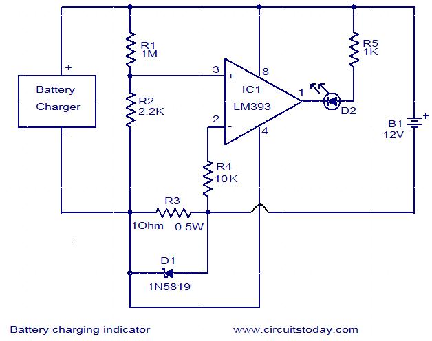
This simple circuit can be used to monitor whether a battery is charging. The voltage comparator IC LM393 is the core component of this circuit. The LED D1 will remain ON whenever there is at least 25 milliampere current...
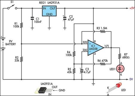
This circuit indicates the remaining battery life by varying the duty cycle and flash rate of an LED as the battery voltage decreases. It indicates five battery conditions: (1) a steady glow indicates that the battery is healthy; (2)...
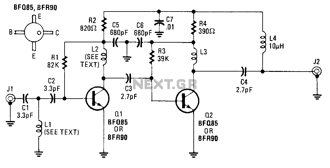
An inexpensive antenna-mounted UHF-TV preamplifier can add more than 25 dB of gain. The first stage of the preamplifier is biased for optimum noise performance, while the second stage is optimized for maximum gain. Additional details include Ll and...
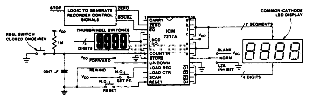
This circuit illustrates various applications of up/down counting for monitoring dimensional position. In the tape recorder application, the LOAD REGISTER, EQUAL, and ZERO outputs are utilized to control the recorder. To ensure the recorder stops at a specific point...
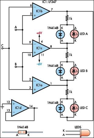
This circuit indicates which of three voltages, ranging from approximately -4V to +4V at points A, B, and C, is the highest by illuminating one of three indicator LEDs. Alternatively, it can be configured to indicate the lowest of...
This small circuit is a linear amplifier for driving small UHF TV transmitters. Its gain is 7 dB and can amplify a signal between 450-800 MHz. You can drive the circuit with 1 to 1.5 Watts signal. Better use...