
maximum minimum voltage indicator

The circuit utilizes three operational amplifiers that serve as voltage comparators to determine the relative magnitudes of the three input voltages. Each op-amp is configured to compare two input voltages at a time, with the output indicating which input voltage is greater. The outputs of these comparators are connected to the anodes of the respective indicator LEDs, while the cathodes are connected to ground through 1kΩ resistors, limiting the current to safe levels for the LEDs.
When voltage A is greater than both B and C, the output of IC1c (which compares A and B) will be low, and the output of IC1b (which compares A and C) will be high, resulting in the illumination of LED A. Conversely, when B is the highest voltage, the outputs will indicate accordingly, lighting LED B. The same logic applies to LED C when C has the highest voltage.
The design also accommodates alternative configurations. By reversing the connections of the LEDs and the 1N4148 diodes, the circuit can be modified to indicate the lowest voltage. This is achieved by making use of the inherent characteristics of the comparators, which will now indicate the condition where all inputs are compared in reverse. Furthermore, if the 1N4148 diodes are replaced with additional LEDs, the circuit can simultaneously indicate both the highest and lowest voltage inputs, providing a versatile solution for voltage level indication in various applications.
This circuit is particularly useful in applications where monitoring multiple voltage levels is critical, such as in battery management systems, voltage monitoring in power supplies, or any scenario requiring comparative voltage analysis. The simplicity of the design, combined with the flexibility of configurations, makes it a valuable tool in electronic circuit design.This circuit indicates which of three voltages in the range from about about -4V to about +4V - at A, B and C - is the highest by lighting one of three indicator LEDs. Alternatively, it can be wired to indicate the lowest of three voltages or to indicate both the highest and lowest voltages.
Op amps IC1a, IC1b & IC1c are wired as comparators, whil e the three indicator LEDs and their series 1kO current limiting resistors are strung across the op amp outputs to implement the appropriate logic functions. For example, LED A will light only when pin 8 of IC1c is low (ie, A greater B) and pin 7 of IC1b is high (ie, A greater C).
Similarly, LED B will light only when pin 8 of IC1c is high (ie, B greater A) and pin 1 of IC1a is low (ie, B greater C). LED C works in similar fashion if the voltage at C is the highest. Note that if all the LEDs and their parallel 1N4148 diodes are reversed, the circuit will indicate the lowest of the three input voltages.
And if each 1N4148 diode is replaced by a LED, the circuit will indicate both the highest and lowest inputs. 🔗 External reference
Related Circuits
A simple power operational amplifier circuit designed for operation up to 300 Hz. One variant of this circuit presents challenges in protecting the flow regulator due to its fixed nature, rendering standard protections ineffective. The circuit is intended to...

An AC-coupled unity gain voltage follower operating on a single supply is illustrated. The voltage divider network consisting of resistors R1 and R2 provides a DC voltage equal to half the supply voltage to the non-inverting input of the...
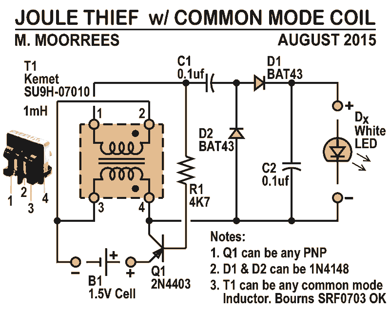
Like all joule thieves, this circuit boosts the voltage from a single 1.5V dry cell battery high enough to illuminate ultrabright GaN blue, green, or white LEDs. Instead of requiring a custom coil, it utilizes an off-the-shelf standard Kemet...
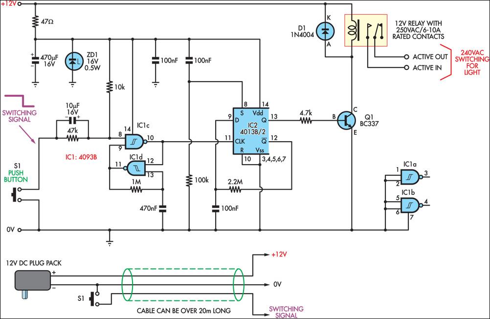
This circuit enables the remote control of a 240V mains appliance, such as a light bulb, through low-voltage cabling and a pushbutton switch. The mains appliance is activated using a suitably-rated relay. All electronic components are housed in an...
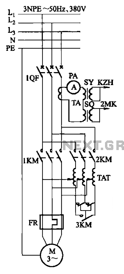
Autotransformer voltage starting, with an adjustable starting time of 30-60 seconds. It includes the SDJ electrode liquid level sensor of HJ-13 type, a pump control system box of HKD-21B type, 1MK level modules adopted by HKG-1SG type, 2MK start...
A novel supply voltage monitor which uses a LED to show the status of a power supply. This simple and slightly odd circuit can clearly show the level of the supply voltage (in a larger device): as long as...