
UJT RELAXATION OSCILLATOR

The operation of the Uni-Junction Transistor (UJT) is characterized by its unique structure and behavior, which is particularly useful in timing and triggering applications. The UJT consists of a single n-type semiconductor bar with two p-type regions, referred to as Base1 and Base2. The emitter terminal is connected to the n-type material and plays a crucial role in the device's operation.
When the voltage at the emitter reaches a specific threshold, denoted as Vp, the UJT becomes active. Prior to reaching this voltage, the emitter remains isolated from the two bases, preventing any current flow. The isolation ensures that the device remains in a non-conductive state, which is essential for its function in timing circuits and oscillator applications.
Once the voltage at the emitter exceeds the threshold value, the UJT turns ON, allowing current to flow between the emitter and Base1 or Base2. This transition marks the beginning of the conduction phase, where the UJT can be used to trigger other devices or control circuits. The characteristics of the UJT, including its negative resistance region, allow it to oscillate or switch, making it a valuable component in various electronic applications.
In practical applications, the UJT can be used in relaxation oscillators, pulse generators, and timing circuits. The precise control of the conduction state based on the emitter voltage makes it an essential component in designing circuits that require timing and triggering functionalities. Understanding the behavior of the UJT during the transition from non-conductive to conductive states is crucial for engineers when integrating this device into electronic systems.At the point Vp the Emitter triggers and TURN the ujt ON, until this point ; the emitter is isolated(doesnt conduct) from the transistor so no Current Conduction occurs between Base1 and Base2. 🔗 External reference
Related Circuits

A voltage-controlled oscillator using the NE555. This circuit is commonly referred to as a voltage-to-frequency converter because the output frequency is altered by varying the input voltage. As previously noted, pin 5 serves as the voltage control terminal, which...
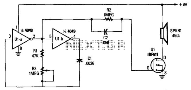
Two gates, U1A and U1B, of a 4049 hex inverter, are connected in a VFO circuit. Components R1, R3, and C1 set the frequency range of the VFO. With the given values, the circuit's output can range from a...
This circuit was designed to drive an impact counter, utilizing the ICL8038 as its core component. It is intended for a motor that operates a conveyor, with the motor featuring a feedback system known as a tachogenerator. Only a...
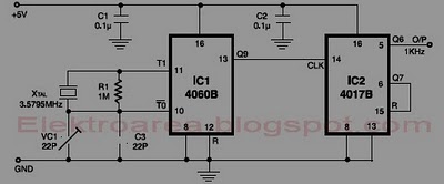
This circuit is designed for accurate time-base generation utilizing the commonly available 3.5795 MHz crystal, which is frequently used in telecommunication equipment. A crystal-based oscillator combined with a divider IC chain or a similar circuit, such as an ASIC,...
Understanding how quartz-crystal resonators operate can lead to designing crystal oscillators with improved stability and better noise performance. Quartz-crystal resonators function based on the piezoelectric effect, where mechanical stress applied to a quartz crystal generates an electrical charge. This property...
The operational amplifier Wien-bridge oscillator offers insight into classic oscillator design through feedback analysis. Feedback analysis determines whether a circuit is stable or unstable. In amplifier design, particularly for high-speed applications, avoiding conditions that lead to oscillation is crucial....