
Ultra-Flanger guitar effect

The circuit described is a flanger effect pedal that combines features from both the EH Electric Mistress and the MXR flanger, while also incorporating the wide sweep characteristic of the A/DA flanger. The design aims to achieve versatility and a rich sound palette, making it suitable for various musical applications. The inclusion of an additional integrated circuit allows for the extended sweep range, enhancing the modulation capabilities of the effect.
Power consumption ranges between 2 to 8 milliamps, which is efficient for a pedal of this nature, with the current draw primarily influenced by the clock frequency used in the modulation process. This low current consumption is advantageous for battery-operated applications and ensures longer operation without frequent battery replacements.
The circuit features a manual sweep function that allows users to control the modulation depth. A significant update noted in the development process indicates that the manual sweep circuit should connect to ground rather than a reference voltage (vref). This adjustment is crucial for correct operation and performance of the flanger effect.
Additionally, the feedback loop of the circuit is adjustable via a feedback limiting resistor, which was modified from 100K to 270K. This alteration is intended to refine the feedback characteristics, particularly the bass response within the flanger effect. The capacitor in series with this resistor plays a critical role in shaping the tonal qualities of the feedback signal, thus directly influencing the onset point of the flanging effect. Experimentation with this component can lead to variations in sound, allowing for a more personalized tone. Overall, this circuit represents a thoughtful balance of simplicity and complexity, catering to the needs of musicians seeking a versatile flanging effect.I was originally going to develop a minimum part count version of the EH Electric Mistress. Instead I went for a something with the versatility of an MXR flanger and the extra wide sweep that the A/DA flanger was known for. It needed an extra chip to get the wide sweep but it's worth it. Current consumption is very reasonable at around 2 to 8 milliamps dependent upon clock frequency. 7th April 2002: I have made a major correction to the schematic as a result of getting a second board going. The manual sweep circuit should return to ground not vref. I also increased the feedback limiting resistor from 100K to 270K. This area of the circuit might bear some experimentation as the cap in series with that resistor determines the amount of bass in the feedback signal which affects the onset point.
🔗 External reference
Related Circuits
This schematic represents a simple JFET buffer derived from the Basic Buffers article in the AMZ Lab Notebook, enhanced with pulldown resistors at both the input and output. The circuit features high input impedance and low output impedance, making...
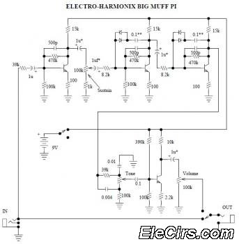
The Electro Harmonix Big Muff Pi circuit would likely benefit from the incorporation of a modern input-jack power connection and a DPDT bypass switch. The specific types of transistors and diodes used in the circuit are not specified. It...
The Echorec delay is an impressive piece of engineering. In their pursuit of perfection, Binson successfully addressed many critical design aspects, achieving a balance between simplicity and the integration of genuinely useful features in this classic echo machine. The...
The schematics on this page are provided strictly for educational purposes. If anyone intends to use these designs for profit, they are required by law to obtain permission from the legal owner(s) of the design and comply with any...
This tutorial covers the Hall Effect Sensor and Magnetic Hall Effect Switch, which are output transducers utilized for detecting magnetic fields. The Hall Effect Sensor operates based on the principle that a voltage is generated across a conductor when it...
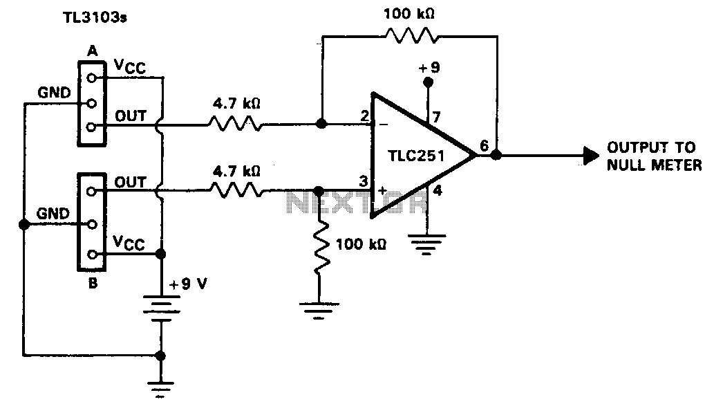
The TL3103 linear Hall-effect device can be used as a compass. By definition, the north pole of a magnet is the pole that is attracted to the magnetic north pole of the Earth. The north pole of a magnet...