
Ultrasonic ranging

The Ping Ultrasonic Distance Sensor operates on the principle of echolocation, utilizing ultrasonic sound waves to measure distances. The sensor's operation begins with the application of a brief 5V pulse to the I/O pin, which initiates the measurement cycle. After the specified delay, the sensor emits a pulse of ultrasonic sound. The time taken for the sound to travel to the nearest object and return is measured by monitoring the state of the I/O pin. This duration is critical, as it is directly proportional to the distance of the object from the sensor.
For practical applications, it is essential to account for the sensor's limitations, including its effective range and the influence of environmental factors such as temperature and angle of incidence. The sensor's range can be affected by obstacles in the path of the ultrasonic waves, and the angle at which the waves hit a surface can lead to inaccurate readings.
The use of external triggers RB0 and RB1 allows for efficient monitoring of the I/O pin's state changes, facilitating precise timing for distance calculations. The integration of Timer 1 in the system provides accurate timing measurements, which are crucial for calculating the distance based on the speed of sound. The calculated distance can be further processed or displayed using an LCD or communicated to a PC via RS-232, making the sensor versatile for various applications, including robotics, distance measurement, and obstacle detection.
The sensor's design also includes a refractory period, ensuring that it does not attempt to measure distances too frequently, which could lead to erroneous readings. The implementation of the temperature compensation formula allows for adjustments in the speed of sound based on environmental conditions, enhancing measurement accuracy. In summary, the Ping Ultrasonic Distance Sensor is a robust and reliable component for distance measurement applications, provided that its operational parameters and environmental influences are carefully managed.The Ping Ultrasonic Distance Sensor by Parallax has three pins. These pins are +5V, I/O, and Ground. In order to activate the sensor, a 5 microsecond 5V signal must be sent to the I/O pin. The sensor then waits 750 microseconds before sending an ultrasonic wave. The sensor sets the I/O pin to high (+5V). When the sensor receives the reflected ultr asonic wave, it sets the I/O pin to low. The time that the I/O pin is high represents twice the distance of the object, as the wave must travel to the object and be reflected back. The sensor is rated for 2cm to 3m, though it will measure distances as far as 3. 47m. After the sensor has received a signal there is a 200 microsecond refractory period. Due to the delay and the refractory period, one must wait 19. 455 milliseconds between successive measurements (18. 5 milliseconds to measure 3m + 5 microseconds to active the sensor + 750 microsecond delay + 200 microsecond refractory period).
Charts diagramming the effects of elevation and angle of the object relative to the sensors can be found in the product documentation ( [1] ). In the circuit, the black wire represents ground. Pin C5 was used as the output pin responsible for activating the sensor. The external triggers RB0 and RB1 were used to identify when the I/O pin of the sensor was set to high and low respectively.
Pin C6 is used for RS-232 communication to the PC. In order to setup LCD output, see C Example: Parallel Interfacing with LCDs. This interrupt will be activated when external trigger RB1 transitions from High to Low. This function will retrieve the time from Timer 1. It will then calculate the distance of the object. The. 0000004 term represents the. 8 microsecond increment of Timer 1 divided by 2. Division by 2 is required since the wave must travel twice the distance that is being measured. The speed of sound is estimated as 343 m/s at room temperature. If there is a temperature sensor, the speed of sound can be calculated as follows: Csound = 331. 5 + (. 6 * TCelsius). The if statement is used to prevent the detection of the activation signal. 🔗 External reference
Related Circuits
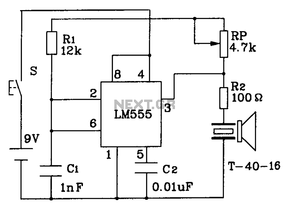
The circuit described is a 555 ultrasonic transmitter constructed to emit ultrasonic signals at a frequency of 40 kHz. It operates by generating oscillating pulse outputs from a 555 timer (specifically the T-40-16 model). The circuit is designed to...
This circuit operates using ultrasonic sound, which is sound at frequencies above 20 kHz, making it inaudible to humans. The circuit generates ultrasonic sound frequencies between 40 kHz and 50 kHz. Similar to other remote control systems, this circuit...
The following circuit illustrates an Ultrasonic Sensor Circuit Diagram. This circuit is based on the MAX232 IC. Features include a quiescent current of 150mA. The Ultrasonic Sensor Circuit utilizes the MAX232 integrated circuit, which is primarily designed for converting signals...
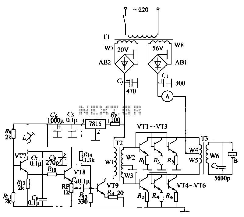
The ultrasonic drilling machine is essential machinery in the dairy industry for processing jewelry, primarily for natural stones, crystal agate, jade, and glass products. This machine is particularly effective for high-hardness materials, enabling both drilling and engraving. The following...
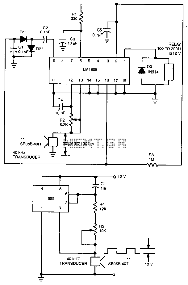
This ultrasonic transmit/receive circuit operates at 40 kHz. Control resistor R5 adjusts the frequency for optimal performance with the transducers used. The ultrasonic transmit/receive circuit designed to operate at a frequency of 40 kHz is essential for applications in distance...
This project has numerous practical applications in security and alarm systems for homes, shops, and vehicles. It features a set of ultrasonic transmitter and receiver operating at the same frequency. When an object moves within the area covered by...