
Ultrasonic Receiver Sircuit Diagram

The ultrasonic receiver circuit utilizes the CA3140 operational amplifier, known for its high input impedance and low noise characteristics, making it suitable for sensitive applications such as ultrasonic signal detection. The circuit typically incorporates a piezoelectric transducer that converts ultrasonic sound waves into electrical signals.
When ultrasonic waves strike the transducer, it generates a small voltage signal corresponding to the frequency of the incoming sound. This signal is then fed into the CA3140, which amplifies the voltage to a more usable level. The gain of the amplifier can be adjusted through external resistors, allowing for flexibility in sensitivity based on the application requirements.
The output of the CA3140 can be further processed or analyzed, often interfacing with microcontrollers or signal processing units for tasks such as distance measurement or object detection. Additional components such as filters may be included in the circuit to eliminate noise and improve the clarity of the received ultrasonic signals.
Overall, the CA3140-based ultrasonic receiver circuit serves as an essential tool in various applications, including robotics, automotive systems, and industrial automation, where precise distance sensing and object detection are critical.The following circuit shows about Ultrasonic Receiver Sircuit Diagram. Thicircuit based on the CA3140IC. Features: The frequency of sound produced .. 🔗 External reference
Related Circuits
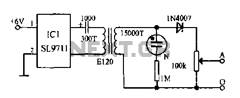
The electronic frostbite treatment instrument ASIC SL9711 consists of an oscillation circuit, a power amplifier, and a controller. It generates a sine wave at frequencies of 100 Hz and 3 Hz, followed by a step-up transformer with potentiometer adjustment...
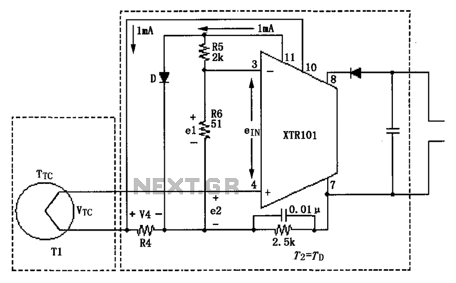
The circuit illustrated in the figure features two temperature zones and incorporates a thermocouple cold-junction compensation diode input circuit. It utilizes a J-type thermocouple as the temperature sensor. A semiconductor diode (D) is configured to provide cold junction compensation...
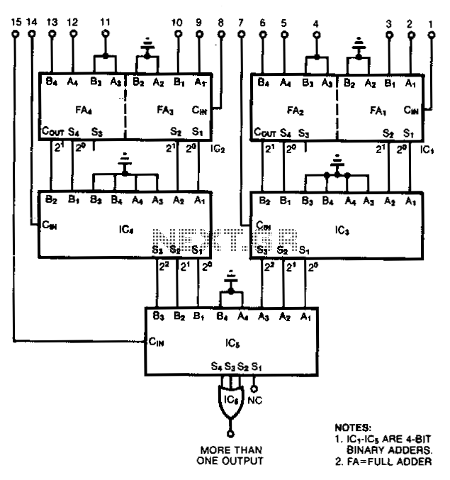
This RS-232 type line receiver is designed to drive CMOS logic and incorporates a Schmitt-trigger feedback network that provides approximately 1-V input hysteresis, enhancing noise immunity. A potential issue in an interface connecting two devices, each connected to different...
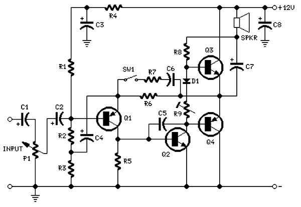
The circuit is intentionally designed using older type transistors to achieve harmonic distortion and to mitigate the challenges of sourcing high-quality components. The amplifiers can be easily powered by a plug-in wall transformer rated at 12V. When SW1 is...
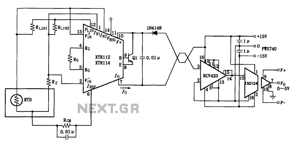
The RTD temperature data collected at the scene is converted into a voltage using the XTR112/114. This voltage is further transformed into a 4 to 20 mA current output, which is then transmitted via a twisted pair. The RCV420...
The following circuit illustrates the circuit diagram of a motor control unit. This circuit is based on the LM317 integrated circuit (IC). Features include diodes that protect the regulator. The motor control unit circuit utilizes the LM317 voltage regulator to...