
Unijunction Transistor Tutorials

The unijunction transistor (UJT) operates based on its unique structure, allowing it to function effectively as a relaxation oscillator. The device features a single P-N junction that creates a characteristic negative resistance region, making it suitable for generating oscillatory waveforms. The operation begins with the application of a voltage to the emitter, which is critical for the triggering of the device.
In practical applications, the capacitor C is charged through the resistor R1 at a rate determined by the RC time constant. The value of R1 and the capacitance of C directly influence the frequency of oscillation. As the voltage across C rises, the emitter voltage eventually reaches the threshold of 0.6 volts, causing the UJT to switch from a high-resistance state to a low-resistance state. This transition allows the capacitor to discharge rapidly, creating a sharp pulse of voltage.
The output pulse generated across R3 can be utilized for various applications, including triggering other circuits or providing timing signals. The sawtooth waveform produced across C can be further processed or filtered depending on the specific requirements of the application. The simplicity and effectiveness of the UJT in generating oscillations make it a valuable component in electronic circuits where timing and waveform generation are essential.
In summary, the unijunction transistor serves as a versatile component in electronic design, enabling the creation of oscillatory signals through its unique characteristics and operational principles.The unijunction transistor (UJT) is made of a bar of N type material with a P type junction (the emitter) near the centre. Base 1 is connected to zero volts and base 2 to the positive supply. The resistance between the two bases (the INTERBASE RESISTANCE) is typically 10k. With the emitter unconnected, the bar acts as a potential divider, and abou t 0. 5 volts appears at the emitter. If a voltage is connected to the emitter, as long as it is less than 0. 5 volts, nothing happens, as the P-N junction is reversed biased. (see the right hand diagram). When the emitter voltage exceeds 0. 5 volts, the junction is forward biased and emitter current will flow. This increase in current is equal to a reduction of resistance between base 1 and the emitter. In the circuit, C charges via R1. When the voltage across C exceeds 0. 6 volts, the b1/emitter junction goes low resistance and discharges C. The result is a sawtooth waveform across C. There is also a pulse of current through R3, giving a pulse of voltage across it. This circuit is called a relaxation oscillator. The voltage across C charges up slowly then suddenly relaxes. 🔗 External reference
Related Circuits
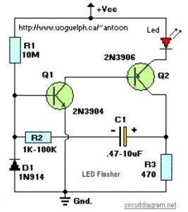
This circuit is designed to flash a high-brightness red LED (5000 mcd), making it suitable for use in fake car alarms or other devices intended to attract attention. The specific values of the components are not critical, allowing for...
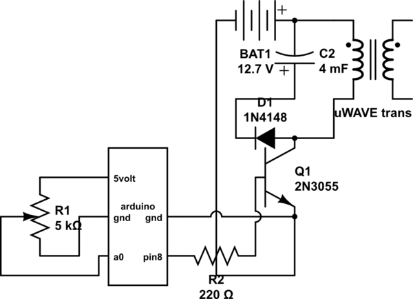
If both devices need to be powered from the battery, should the emitter be connected to the ground of the Arduino and the battery to prevent current from flowing through the Arduino ground, ensuring a clean pulse? Alternatively, can...
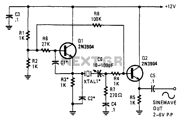
This oscillator employs two transistors and operates the crystal in its fundamental mode. Capacitors CT and C2 should be approximately 2,700 pF for 1 MHz, 680 pF for 5 MHz, and 330 pF for 10 MHz. A capacitance of...
Most surviving TR-1 radios no longer function. Many collectors prefer to maintain them in their original condition to preserve authenticity. However, there may come a time when one wishes to hear the radio play. Before proceeding with any modifications,...
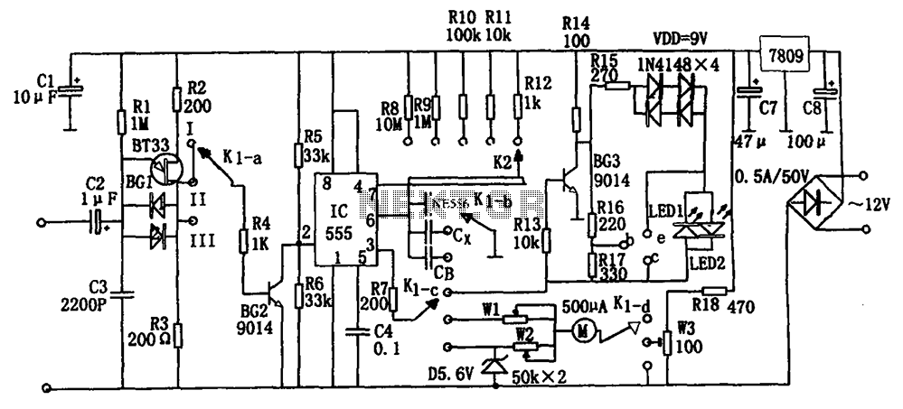
The frequency detection circuit utilizes a transistor line, adjustable via a preset switch K1, to convert capacitance and frequency measurements. The K1 switch is positioned to detect capacitance. The circuit comprises components including a 555 timer, resistors R8 to...
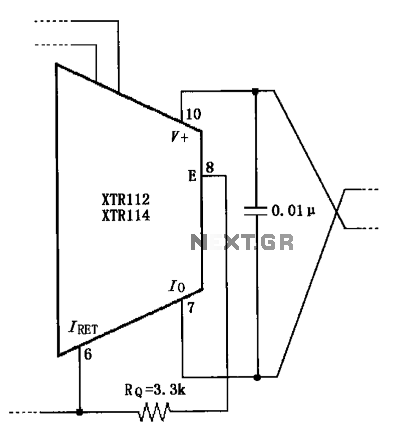
When not using the external transistor Q1, a 3.3k resistor should be connected between the pins and legs. This connection causes internal power dissipation, which will affect accuracy and lead to a decline in performance. The circuit in question involves...