
XTR112 114 without external transistor circuit diagram

The circuit in question involves the use of a 3.3k resistor connected to the pins and legs of a component when the external transistor Q1 is not utilized. This configuration is critical in maintaining the circuit's functionality. However, it is important to note that the internal power dissipation resulting from this setup can negatively impact the accuracy of the circuit's performance.
In electronic circuits, power dissipation occurs when electrical energy is converted into heat. In this case, the 3.3k resistor plays a significant role in limiting the current flow, which is essential for protecting sensitive components. However, as the resistor dissipates power, it generates heat, which can lead to thermal drift and inaccuracies in the circuit's output.
To mitigate the effects of power dissipation on accuracy, careful consideration should be given to the resistor's placement and the overall thermal management of the circuit. This may involve using heat sinks, selecting components with higher power ratings, or redesigning the circuit to minimize the heat generated.
Additionally, it may be beneficial to evaluate the necessity of the external transistor Q1 in the circuit. If Q1 can be used effectively, it may help reduce the reliance on the resistor, thereby improving accuracy and performance.
In summary, while the connection of a 3.3k resistor is necessary when the external transistor Q1 is not present, attention must be paid to the implications of internal power dissipation on the circuit's accuracy. Proper design practices and thermal management techniques should be employed to ensure optimal performance. As shown, when not in external transistor Q1, connect a 3.3k resistor between feet and legs. With this connection circuit due to internal power dissipation affect accuracy will decline.
Related Circuits
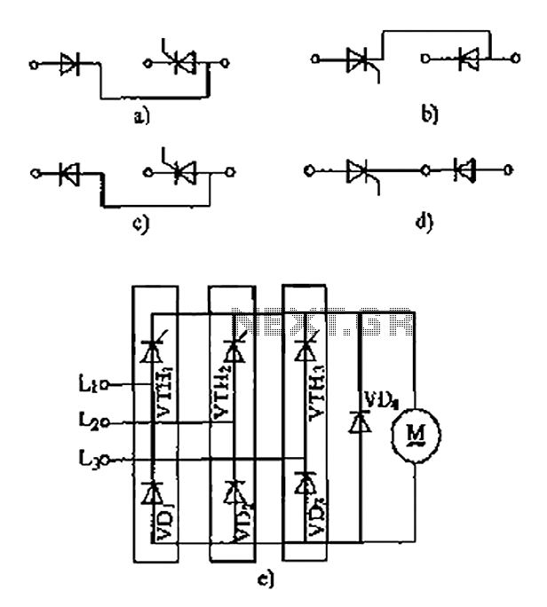
The thyristor linking arm rectifier module is a three-phase half-controlled bridge rectifier circuit. The thyristor-rectifier module linking arm consists of a thyristor and a rectifier diode connected in series or parallel, designed to fulfill specific requirements in power circuits....

The circuit is constituted by the RF2324 1880MHz internal amplifier collector bias application. A radio frequency (RF) signal enters through input pin 3 and is processed by a preamplifier. The final stage power amplifier output is amplified by 7...

The Joule thief circuit is well-known among electronics enthusiasts. It has numerous implementations, but the most common is a very minimalist voltage booster. In the simulation file, a 1.5V battery is attached, which is the voltage of a new...
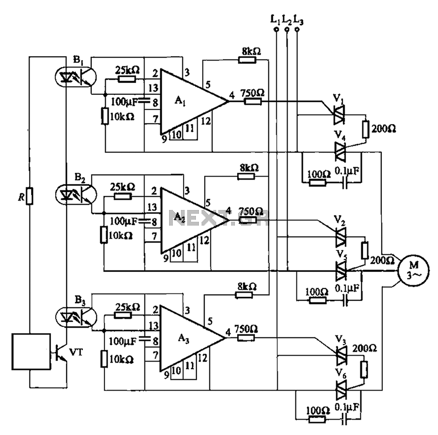
The 331 circuit depicted in the figure utilizes a two-way thyristor for controlling the start and stop functions of a motor. It operates without mechanical contacts, generating no noise or sparks, making it suitable for applications that require frequent...
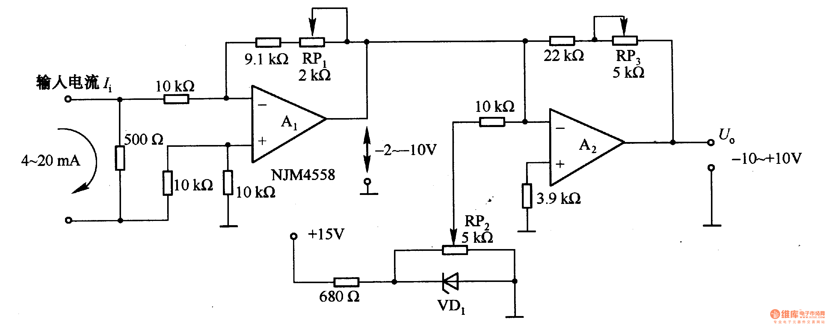
Figure 1-42 (a) is a voltage/current conversion circuit that converts a 0-10V input voltage into a 4-20mA output current. Adjusting resistor RP2 can set the input voltage (Ui) to 0V, resulting in an output current (I) of 20mA; similarly,...
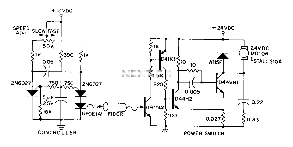
A DC power supply can be controlled through an optical fiber. The circuit includes a small DC motor (1/12 hp) that offers an isolated speed control channel. The control logic operates as an independent module, consuming 300 mW of...