
Intercom Circuit

The intercom circuit employs two main components: the 8-ohm mini speakers and the press-to-talk (PTT) switches. Each station in the intercom system consists of a speaker and a PTT switch. When the PTT switch is pressed, it completes the circuit, allowing audio to be transmitted through the speaker. The spring-return feature of the PTT switch ensures that the circuit is only active while the button is pressed, thereby preventing unintended continuous transmission.
To maintain audio clarity and prevent issues such as motor-boating, a separate power supply is recommended for the speakers. This separation helps to isolate the audio circuit from the power supply variations that could introduce noise or instability in the system. The power supply should be capable of delivering the appropriate voltage and current required by the 8-ohm speakers, which typically operate at low power levels.
The intercom design is modular, allowing for the addition of extra stations. Each additional station can be connected in parallel to the existing stations, provided that the total load does not exceed the power supply capacity. Careful consideration should be given to the wiring layout to ensure that signal integrity is maintained across all connected stations.
In summary, this simple intercom circuit design is effective for basic communication needs, utilizing readily available components while ensuring reliable operation through proper power management and switch design.This is a simple form circuit for a 2-station intercom using common 8R mini speakers. The press-to-talk switches should have a spring-return so the intercom can never be left ON. This is the figure of the circuit; Power the speaker from a separate power supply is the secret to preventing instability (motor-boating) with a high gain circuit like this. An extra station (or two extra stations ) can be connected to this design. 🔗 External reference
Related Circuits
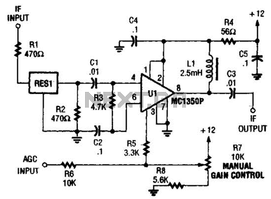
The ZN416E can be configured as a simple 455-kHz IF amplifier. In this case, the circuit's center and bandwidth are set by RES1 (a Murata CSB455E ceramic resonator). The ZN416E is a versatile integrated circuit designed for use as a...
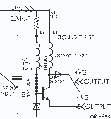
This circuit diagram is provided for those interested. It is a small circuit that takes an input of 1.5 volts and outputs 120 volts. The circuit in question is a voltage step-up converter, commonly referred to as a boost converter....
ETl3X220 is a cost-effective single-chip transmitter that operates via RF communication. It supports up to 10 channels and is ideal for applications such as wireless mice, keyboards, and other communication devices. The main technical features include: - Analog FM...
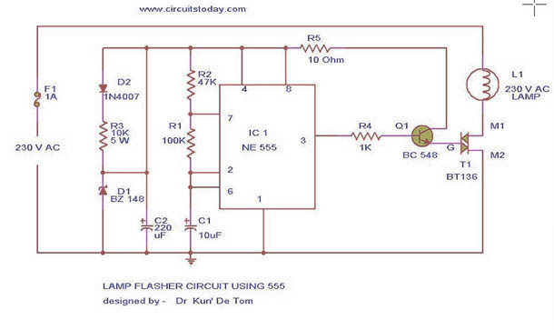
This circuit diagram represents a lamp flasher powered by mains electricity. It is capable of flashing lamps with a maximum power of 200 Watts at user-defined rates. The NE555 integrated circuit is configured as an astable multivibrator, generating the...
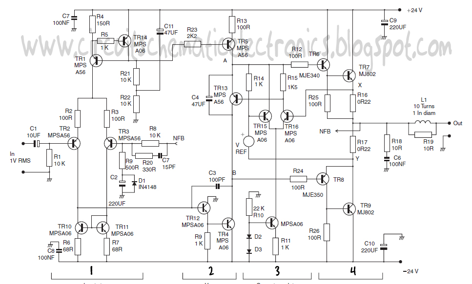
This design schematic represents a Class A power amplifier. It closely matches the operating parameters of Class B to facilitate comparison, particularly with a negative feedback (NFB) factor of 30dB at 20 kHz. The front end is similar to...
This page will be updated as material becomes available. This new system will essentially replace the original BCD design, which was created by WB6IGP and N6IZW and was featured in the ARRL UHF/Microwave Project Manual. Their work was later...