
UNIVERSAL BATTERY CHARGER

The described circuit utilizes a silicon-controlled rectifier (SCR) and an LM317 voltage regulator to manage the charging of a battery while maintaining a switchable operation mode between current regulation and voltage regulation. Initially, when power is supplied, the SCR (SCR1) is non-conductive, and the LM317 functions strictly as a current regulator. The connection of the LM317 to the battery is established through a steering diode (D1), which ensures unidirectional current flow, thus preventing reverse discharge from the battery into the circuit components when power is not present.
The limiting resistor (R1) and bias resistor (R2) are critical for setting the appropriate operating conditions for the LM317. The voltage across the battery is monitored by the trip-point potentiometer (R5), which plays a pivotal role in determining when the SCR will be triggered. As the battery charges, the voltage across R5 increases until it reaches a threshold that activates the SCR, allowing current to flow to ground and transitioning the regulator's operation from current mode to voltage mode.
Once the SCR is triggered, it creates a conductive path for LED1 through resistor R3, illuminating the LED. This visual indication signifies that the circuit has switched to voltage-regulating mode. The operation of the circuit can thus be summarized: the presence of power and the state of LED1 inform users of the current operational mode—current regulation when LED1 is off and voltage regulation when LED1 is on. This design effectively combines battery management with user feedback through LED indication, ensuring efficient charging and operation of the connected load.When power is applied to the circuit, SCR1 is off, so there is no bias-current path to ground; thus, LM317 acts as a current regulator. The LM317 is connected to the battery through steering diode D1, limiting resistor R1, and bias resistor R2.
The steering diode prevents the battery from discharging through the LED and the SCR when power is remov ed from the circuit. As the battery charges, the voltage across trip-point potentiometer R5 rises, and at some point, turns on the SCR. Then, current from the regulator can flow to ground, so the regulator now functions in the voltage mode.
When the SCR turns on, it also provides LED1 with a path to ground through R3. So, when LED1 is on, the circuit is in the voltage-regulating mode; when LED1 is off, the circuit is in the current-regulating mode. 🔗 External reference
Related Circuits

Batteries serve as one of the energy sources available on vessels, utilized during blackouts and emergency situations aboard a ship. These batteries are employed for low-voltage DC systems, such as bridge navigational instruments, and must be kept charged to...

A simple battery charger circuit with reverse polarity indication is presented. The circuit utilizes the L200 integrated circuit, which is a five-pin variable voltage regulator. It can be powered by DC voltage from either a bridge rectifier or a...
This circuit performs a rapid battery test without requiring an external power supply or costly moving-coil voltmeters. It features two testing ranges: when switch SW1 is configured as indicated in the circuit diagram, the device is capable of testing...
The circuit was constructed on a Vero board and tested with a large electrolytic capacitor in place of a battery. A 500-ohm preset resistor determines the output voltage, while a 47k preset resistor regulates the hysteresis and establishes the...
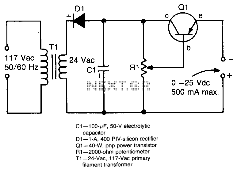
This circuit provides an adjustable output voltage of up to 35 V DC with a maximum output current of 50 mA. The transistor Q1 dissipates significant heat and must be mounted on a heatsink. The circuit in question is designed...
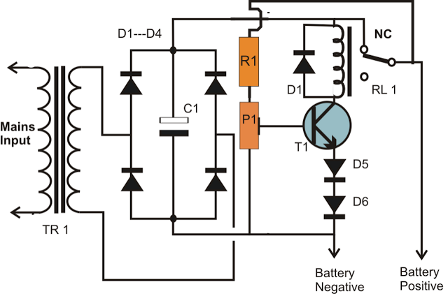
A simple battery charger circuit is described, utilizing a single transistor for voltage detection and automatically disconnecting the battery from the supply when fully charged. The circuit's high voltage trip point is set to switch off the charging voltage...