
Universal DC Mode Motor Drive

The schematic illustrates a DC drive system designed for a universal motor, which is capable of operating on both AC and DC power sources. The primary component of this drive is a diode bridge rectifier, which converts the incoming AC voltage to a stable DC voltage suitable for the motor's operation.
The diode bridge consists of four diodes arranged in a bridge configuration, allowing for the rectification of both halves of the AC waveform. This configuration ensures that the motor receives a continuous DC output, which is essential for its reliable operation. The universal motor can run efficiently on the rectified DC supply, enabling smooth speed control and torque generation.
In addition to the diode bridge, the circuit may include filtering capacitors placed across the output to smooth the rectified voltage, reducing ripple and providing a more stable DC supply. This is crucial in applications where consistent motor performance is required. Furthermore, the implementation of a control circuit, which may include a variable resistor or a microcontroller, can be integrated to adjust the voltage supplied to the motor, allowing for precise speed control.
Protection components, such as fuses or circuit breakers, may also be included in the design to safeguard the motor and the rectifier from overcurrent conditions. Overall, the described DC drive system for the universal motor is an effective solution for applications requiring variable speed control and efficient operation.DC drive for a Universal motor is shown in figure below. In order to supply DC current to the motor, a diode bridge has been added around the motor. The motor.. 🔗 External reference
Related Circuits
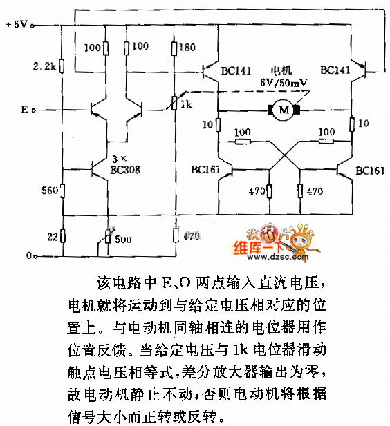
In the circuit, when E and O are input DC voltages, the motor moves to a position corresponding to the voltage. A potentiometer, coaxially connected to the motor, is used for position feedback. When the given voltage equals the...
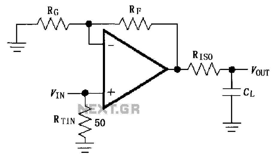
The circuit depicted in FIG demonstrates the MAX4450/4451 utilizing a capacitive load drive circuit with an isolation resistor (RISO). This configuration is situated between the output terminals and the load, along with an additional resistor, to mitigate overshoot and...
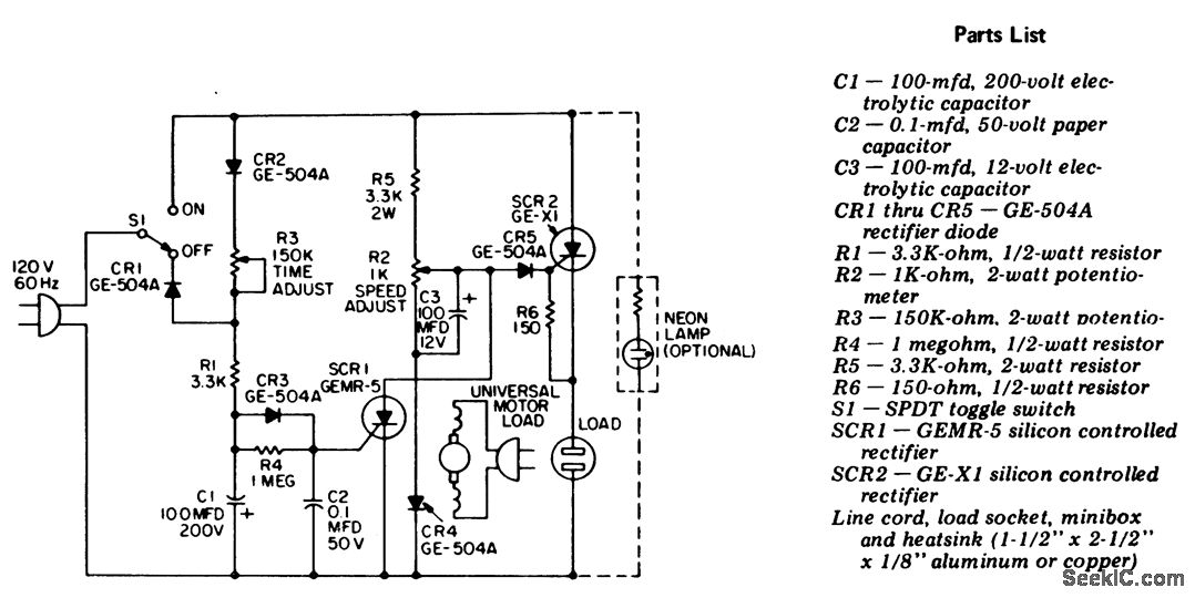
Universal motor control with an integrated self-timer. This circuit is designed exclusively for use with motors that have commutators. When expecting heavy motor loads, it is advisable to replace the GE-X1 with a larger-rated C30B SCR for SCR2. To...
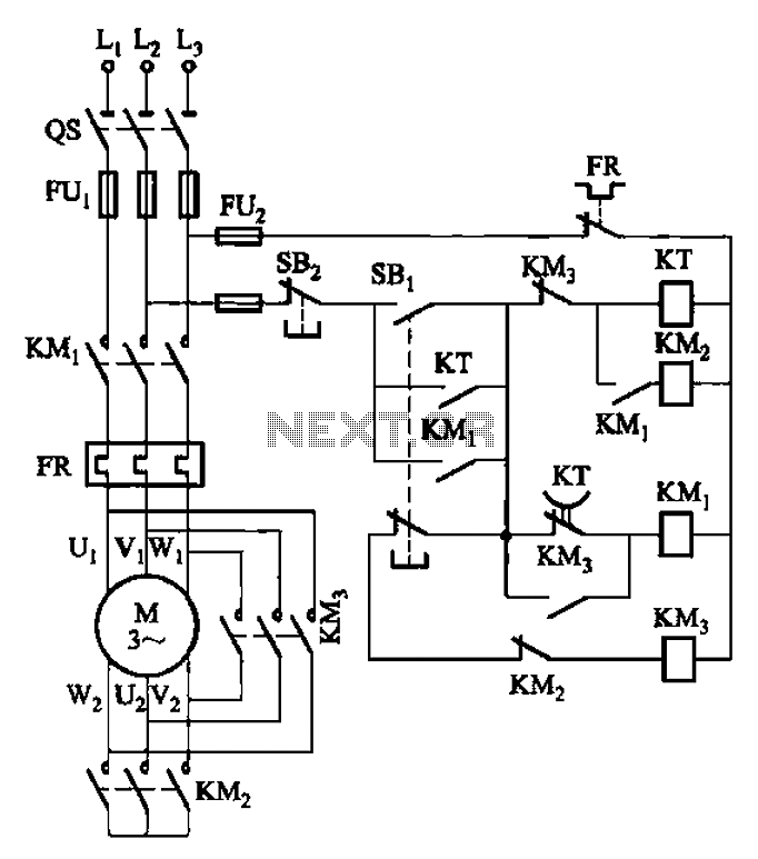
The circuit depicted in Figure 3-41 illustrates a Y-transfer process. When contact KMi is turned off, the motor undergoes a transition in the event of a power failure. Additionally, the main contact KM3 is disconnected when KM2 is activated,...
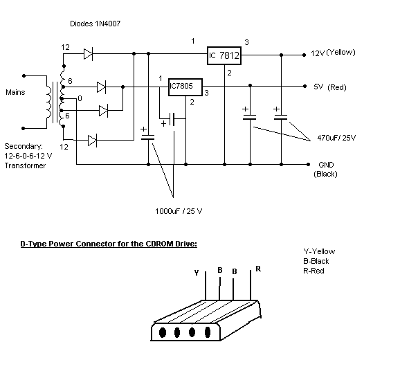
Most of the CDROMS available have an Audio-Out Output to either plug in the headphones or connect it to an amplifier. This circuit enables one to use the CDROM as a stand alone Audio CD player without the computer....

The SC1088 is a bipolar integrated circuit designed for use in mono portable and pocket radios. It is particularly beneficial when a minimal number of peripheral components, which are compact and cost-effective, is essential. The circuit features a frequency-locked...