
Unusual Hall-Effect Oscillators Circuit

The proposed oscillator circuit leverages the properties of the Hall-effect switch, which typically detects magnetic fields but can also generate oscillations under specific configurations. In this setup, the Hall-effect switch is integrated into a feedback loop that influences its own switching behavior, resulting in oscillatory output.
The RC network, composed of resistor R1 and capacitor C1, plays a crucial role in determining the frequency of oscillation. The time constant of the RC network, defined as τ = R1 * C1, directly influences the charge and discharge rates of the capacitor, thereby affecting the frequency of the oscillations produced by the circuit. The oscillation frequency (f) can be approximated by the formula f = 1 / (2πτ), indicating that increasing the resistance or capacitance will lower the frequency, while decreasing them will raise it.
In practical applications, the Hall-effect switch oscillation circuit can be employed in various scenarios, including signal generation, timing applications, and even as a simple clock generator for digital circuits. The simplicity of the design, combined with the ability to easily adjust the frequency through the RC components, makes this circuit a versatile option for engineers seeking to implement oscillatory behavior in their designs.
When implementing this circuit, careful consideration must be given to the specifications of the Hall-effect switch, as well as the values chosen for R1 and C1, to ensure stable oscillation and desired frequency output. Additionally, the layout of the circuit should minimize noise and interference, which can affect the performance of the oscillator. Although not intended for this application, Hall-effect switch can be used as the basis for a rather unusual oscillator. The oscillator can be reconfigured, as shown in Fig. B, to allow the circuit`s oscillating frequency to be controlled via an RC network, comprised of Rl and CI.
Related Circuits
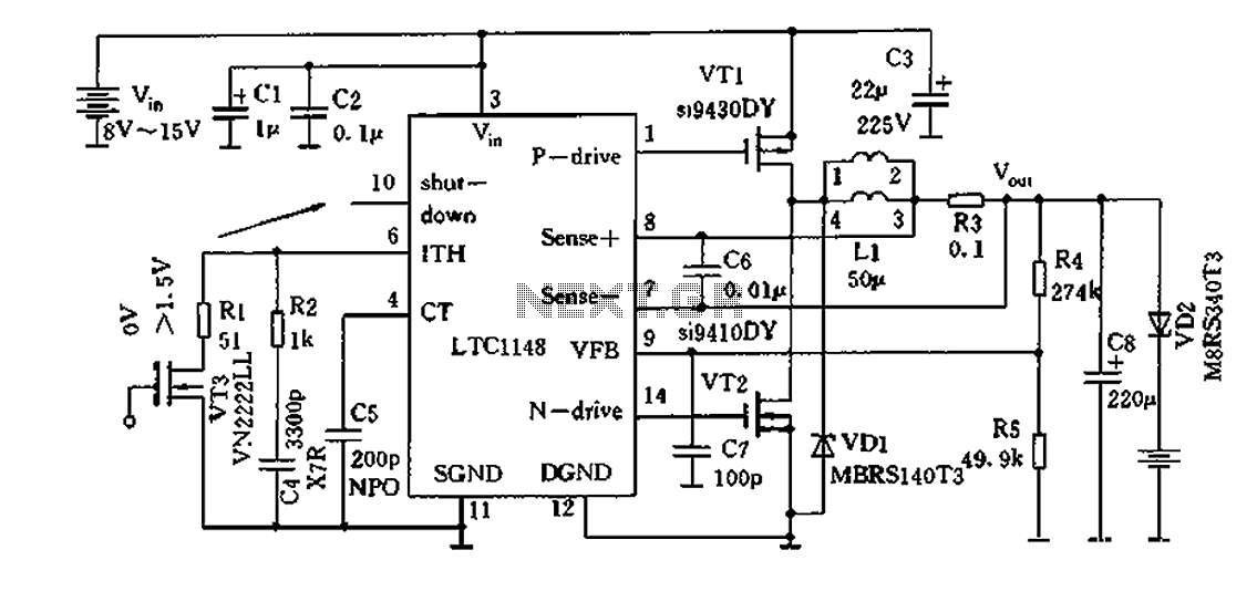
Efficient nickel-cadmium battery charger IC (LTC1148) circuit The LTC1148 is an integrated circuit designed for the efficient charging of nickel-cadmium (NiCd) batteries. This charger IC features a constant current/constant voltage (CC/CV) charging method, which is essential for optimizing the charging...
There have been several requests for a quiz circuit, leading to the development of a design featuring four inputs that can be easily modified. This circuit employs four integrated circuits (ICs) and includes four input circuits with independent outputs,...
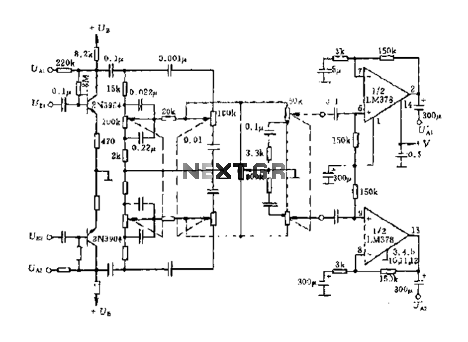
The dual-channel circuit features the LM378 dual operational amplifier and operates with a supply voltage of 24V, supporting an 8-ohm load (or 16 ohms). Each channel delivers an output power of 4W. The circuit includes internal current limiting and...
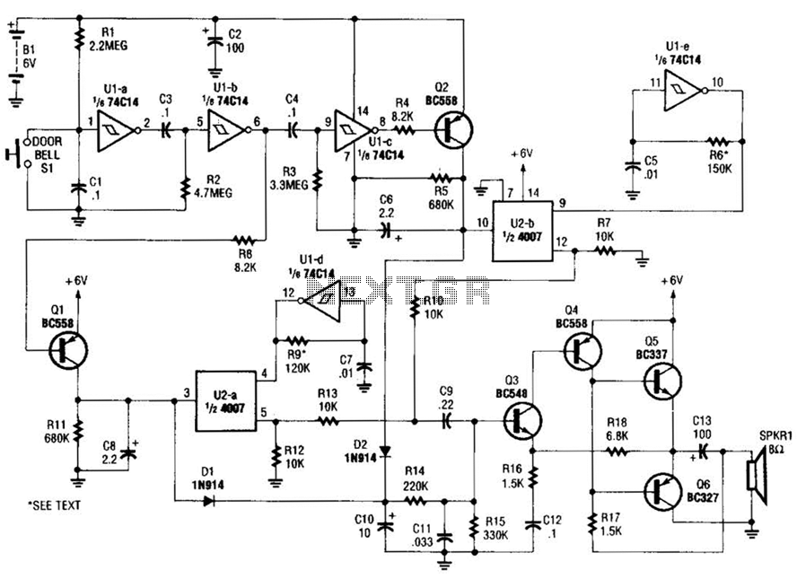
When the doorbell switch is pressed, two monostable stages are sequentially activated, applying bias to a pair of voltage-controlled resistor stages. These stages modulate the outputs from a pair of tone generators. The resulting signals are then fed to...
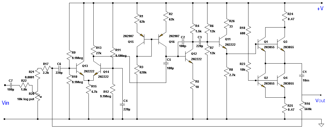
This Class A preamplifier features a symmetrical design. The input differential stages utilize dual transistors, T1 and T2. Polarization correction is crucial due to amplification discrepancies and is managed by transistor T12. Potentiometer P2 adjusts the output voltage to...
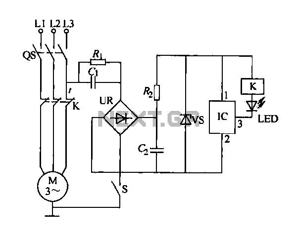
The electric sewing machine saving circuit is designed with a Hall switch integrated circuit (IC) and a relay (K). When the switch is closed, power is activated. The circuit includes a resistor (R) and a capacitor (Ci) for RC...