
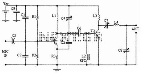
USB FM Transmitter circuit

The USB FM transmitter operates by converting audio signals from a digital source, such as an MP3 player or a computer, into radio frequency signals that can be transmitted over the VHF FM band. The key components of the circuit include a USB power supply, an audio input stage, a modulator, and an antenna.
The power supply section typically utilizes a USB connector to provide 5V DC, which is a standard voltage for USB devices. This power is essential for operating the transmitter's circuitry.
The audio input stage receives the audio signal from the MP3 player or computer through a 3.5mm audio jack. This signal is then conditioned for modulation, ensuring that it is at the appropriate level and impedance for the transmitter.
The modulator is the heart of the FM transmitter, where the audio signal is combined with a carrier frequency. This is usually achieved using a frequency modulation technique, which allows the audio signal to vary the frequency of the carrier wave. Commonly, a transistor or an integrated circuit is used for this purpose, which can efficiently modulate the signal while minimizing distortion.
Finally, the antenna is crucial for radiating the modulated signal into the air, allowing it to be picked up by standard VHF FM radios. The design of the antenna can vary, but a simple wire antenna is often sufficient for short-range transmission.
Overall, the USB FM transmitter is a practical solution for wirelessly transmitting audio from digital devices to conventional FM radios, providing a versatile option for audio playback in various settings.Here is a simple USB FM transmitter that could be used to play audio files from an MP3 player or computer on a standard VHF FM radio by connecting it to an. 🔗 External reference
Related Circuits
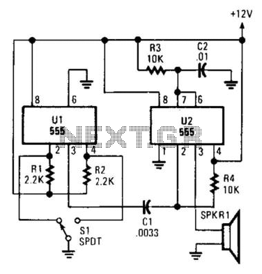
Pulsed sound is produced by this circuit. U1 is used as a bistable multivibrator, which acts as a contact debouncer for S1. C1 feeds a trigger pulse to U2, which then generates a pulse to SPKR1, a piezo transducer....
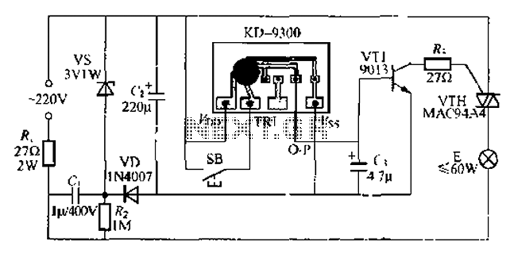
The circuit utilizes a KD-9300 music IC, which activates when the button switch (SB) is pressed, causing the electric lamp (E) to light up for approximately 20 seconds before automatically turning off. The setup includes a half-wave rectifier and...
This circuit functions as a camera switch, allowing multiple cameras to be connected to a single monitor. It can operate in both manual and automatic modes. In automatic mode, the circuit utilizes a 555 astable multivibrator to generate a...
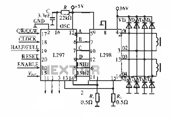
The circuit operates using a dedicated stepping motor controller, the L297. Pin 17 (CW/CCW) is utilized to control the rotation direction of the stepper motor. Pin 18 (CLOCK) regulates the speed of the stepper motor, while pin 19 (HALF/FULL)...
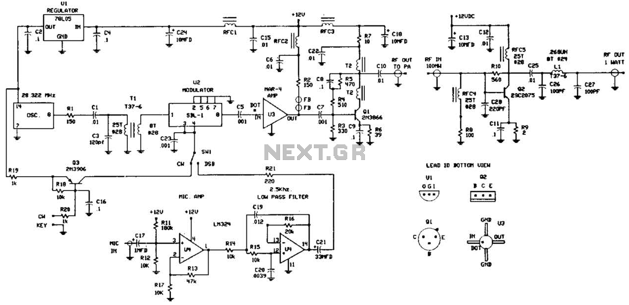
This circuit was detailed in a recent edition of an amateur radio magazine. It enables operation in the 160 to 190 kHz band with a maximum power output of 1 W (license-free) in various modes such as CW, SSB,...
The following diagram illustrates an FM transmitter circuit capable of FM transmission up to 4W. The voltage supply for this circuit ranges from 12V to 16V, with a current consumption between 100mA and 400mA. This circuit operates within an...