
4 Watts FM Transmitter

The FM transmitter circuit is designed to provide reliable transmission of frequency-modulated signals within the VHF band, specifically between 88MHz and 108MHz, which is the standard FM radio band. The circuit typically includes several key components such as a voltage regulator, oscillator, modulator, amplifier, and antenna.
The voltage supply of 12V to 16V is essential for the operation of the circuit, ensuring that all components receive adequate power for optimal performance. The current consumption of 100mA to 400mA indicates that the circuit is efficient, allowing for prolonged use without excessive power draw.
The oscillator is responsible for generating the carrier frequency, which is modulated by the audio signal to create the FM signal. This modulation process typically involves a varactor diode or a similar component that varies the capacitance in response to the audio input, thus changing the frequency of the oscillator slightly to encode the audio information onto the carrier wave.
The amplifier stage boosts the power of the modulated signal, allowing it to achieve the desired output of up to 4W. This output power is sufficient for local broadcasting, ensuring that the signal can be received clearly by standard FM receivers within a reasonable range.
Finally, the antenna plays a critical role in radiating the FM signal into the environment. The design of the antenna should be matched to the operating frequency to maximize efficiency and range.
Overall, this FM transmitter circuit is a valuable tool for various applications, including hobbyist projects, educational demonstrations, and small-scale broadcasting. Proper assembly and tuning of the components will ensure effective operation and compliance with relevant transmission regulations.The following diagram is the FM transmitter circuit with FM transmision up to 4W. Voltage supply for this circuit is 12-16V with current consumption of 100-400mA. This circuit works with frequency of emission range of 88-108MHz. Components.. 🔗 External reference
Related Circuits
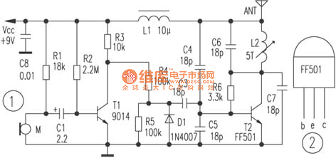
The circuit depicted utilizes a specialized launch tube T2 along with its associated components to create a high-frequency oscillator operating within the frequency range of 88 to 108 MHz. An electret microphone captures the audio signal, which is subsequently...
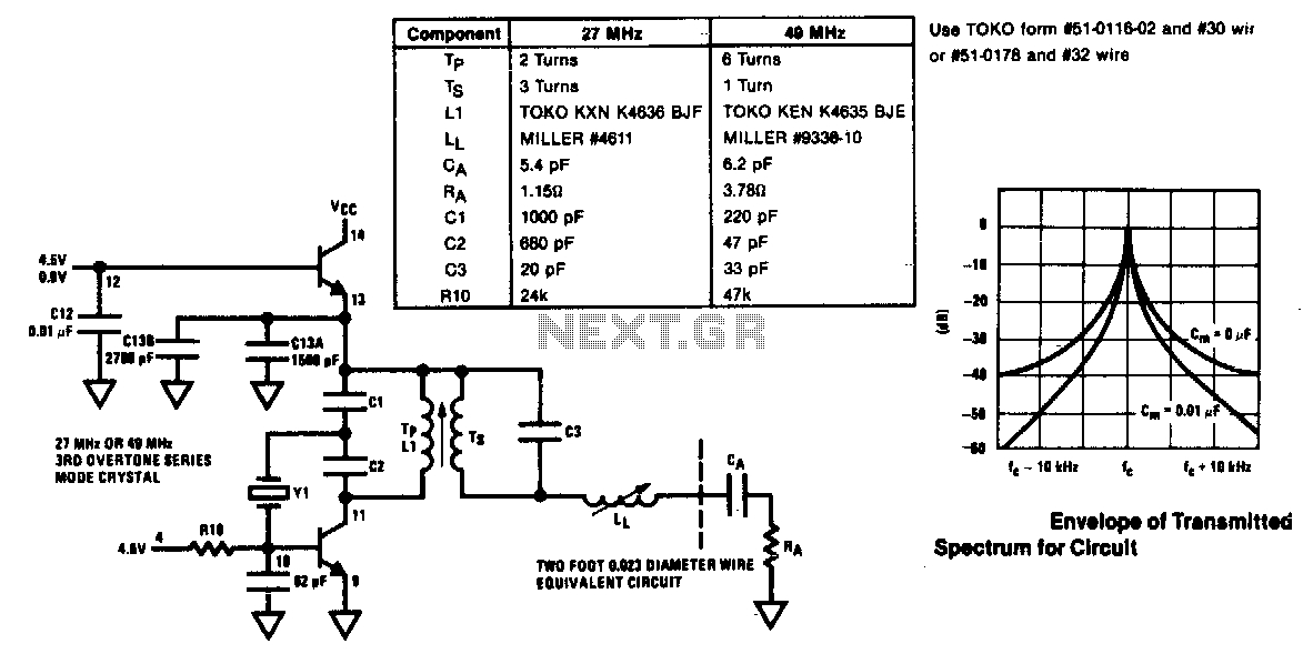
The modulator and oscillator comprise two NPN transistors. The base of the modulator transistor is powered by a bidirectional current source, with the voltage range for the high condition restricted by a saturating PNP collector connected to the pin...

An FM radio generates an interference signal that can be detected on another FM radio tuned 10.7 MHz higher than the original. A 50 kΩ potentiometer is used to adjust the modulation level to its maximum without introducing distortion....
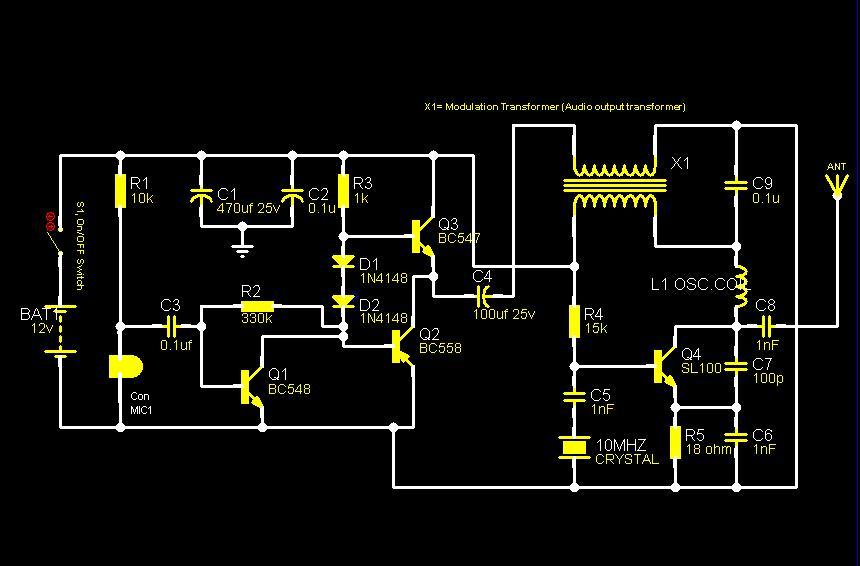
The core component of this circuit is a crystal oscillator utilizing a 10MHz crystal to generate a highly stable carrier frequency. The sound signal from a condenser microphone is amplified by an amplifier circuit comprised of transistors Q1, Q2,...

The circuit presented here represents one half of a device that is highly useful for tracing electrical wiring paths in buildings or locating breaks in wires. This system is based on equipment commonly used by technicians in telephone exchanges....

This circuit diagram is part of an RF circuit. It features an FM transmitter circuit diagram using the BH1417 integrated circuit from RHOM, which incorporates multiple functionalities in a compact design. The IC includes pre-emphasis and a limiter to...