
USB-Powered PIC Programmer

The circuit utilizes a 555 timer IC configured in astable mode to produce a square wave output that serves as the programming voltage for the PIC16F84 microcontroller. The frequency and duty cycle of the square wave can be adjusted by varying the resistors and capacitor connected to the timer. This programming voltage is essential for writing data to the flash memory of the microcontroller.
The circuit typically includes a power supply section that provides the necessary voltage levels for both the 555 timer and the PIC16F84. A resistor-capacitor (RC) network is used to set the timing characteristics of the 555 timer, which directly influences the programming pulse width and frequency. The output from the 555 timer is then routed to the programming pin of the PIC16F84, ensuring that the microcontroller receives the correct voltage levels during programming.
Additional components, such as diodes and transistors, may be included in the circuit to protect against voltage spikes and to control the flow of current to the microcontroller. Proper layout and grounding techniques should be employed to minimize noise and interference, which can adversely affect the programming process.
This circuit design is particularly useful for hobbyists and engineers working with PIC microcontrollers, as it provides a cost-effective and straightforward solution for programming flash memory devices. Careful attention to component selection and circuit configuration will enhance the reliability and performance of the programming process.This simple circuit can be used to program the PIC16F84 and similar “flash memory†type parts. It uses a cheap 555 timer IC to generate the programming vo.. 🔗 External reference
Related Circuits
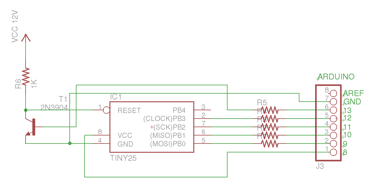
This Arduino sketch is designed to recover ATtiny microcontrollers that have become non-functional due to incorrect fuse settings. It achieves this by placing the affected ATtiny into high-voltage serial programming mode and rewriting the fuses to safe values. The...
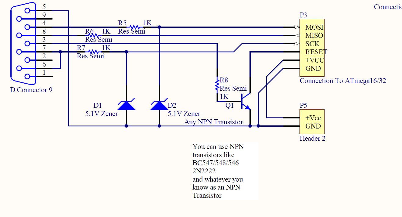
ISP programmer with circuit diagram for AVR Atmega32 microcontroller. This ISP burner circuit is an adaptation of the Pony programmer and uses PonyProg software. The ISP (In-System Programming) programmer designed for the AVR Atmega32 microcontroller facilitates the programming of the...
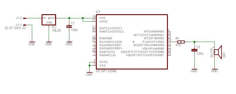
This project enables a PIC microcontroller to play audio PCM sounds using PWM modulation. Pulse-code modulation (PCM) is a digital representation of audio signals. The project utilizes a PIC microcontroller, which is programmed to generate audio signals through pulse-width modulation...

Most of the newer PIC come with the EUSART module which have the function for auto baud rate detection. The features allow a person to set the baud rate at runtime by sending the character "U" or 0x55 to...

It was discovered through experience why the 6V EQ-5 hand controller should not be connected to 12V by mistake. It only took about half a second to damage the hand controller. Upon inspection, it became clear that the large...
Building a serial voltage meter to measure from 0 to 5 volts DC is straightforward. Utilizing MeLabs PicBasic and Microsoft Visual Basic Version 5 Pro is essential, as the MSComm control required for communication is not available in the Visual...