
Water level indicator using 7-segment display circuit design

The water level indicator circuit operates by using the 7408 NAND gate IC to process signals from the five level sensors. Each sensor is strategically positioned at different heights within the tank to monitor the water level accurately. The sensor for common ground serves as a reference point, while the others are calibrated to detect specific water levels: low, half, high, and overflow.
When the water level falls below the low sensor, the circuit activates the corresponding output, illuminating the 7-segment display to show 'L'. As the water level rises and reaches the halfway mark, the half sensor triggers the display to change to 'H'. Finally, once the water level reaches its maximum capacity, the overflow sensor activates, and the display shows 'F' for full.
The 7404 hex inverting gate IC is used to ensure that the output signals are correctly inverted where necessary, allowing for a reliable indication of the water levels. This combination of components creates a simple yet effective water level monitoring system, suitable for various applications, including aquariums, water tanks, and reservoirs. The circuit design is efficient, cost-effective, and can be easily implemented with minimal components, making it an ideal project for both educational and practical purposes.Using this schematic electronic project can be designed a very simple water level indicator electronic circuit that uses a 7-segment display to indicate the water level (low, half and full)in the tank. This water level indicator electronic circuit shows the water level by displaying L, H and F for low, half and full, respectively.
This water level indicator electronic circuit is based on the 7408 quad two inputs and gates IC (that contains four input independent gates) and a 7404 hex inverting gates IC. The circuit uses five level sensors to sense the different water levels ( one for common GND, one for low, one for high one for half and one for overflow ).
🔗 External reference
Related Circuits
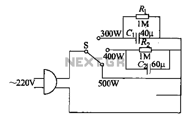
Each family has essential small appliances. The sub-type is an electric power jet, mainly used for clothes and hot shaping. The iron's circuit is shown in Figure 1-30. When using an iron, there is always a concern about using...
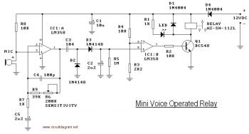
This circuit diagram illustrates a voice-operated relay, which functions similarly to a sound-activated switch circuit. It activates and deactivates the switch based on sound input. The output switch of this circuit is controlled by a relay. The release time...
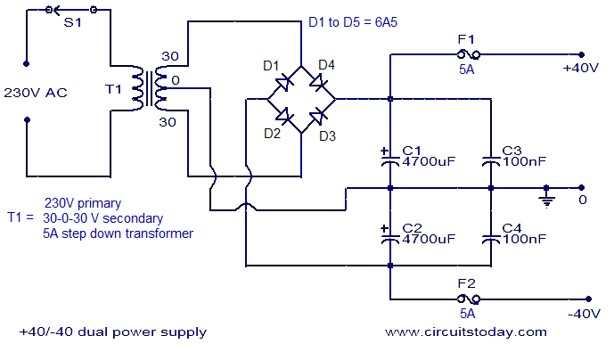
This is an economical 150 Watt amplifier circuit that utilizes two complementary Darlington power transistors, TIP 142 and TIP 147. It is capable of delivering a robust 150 W RMS to a 4 Ohm speaker, offering significant audio output....
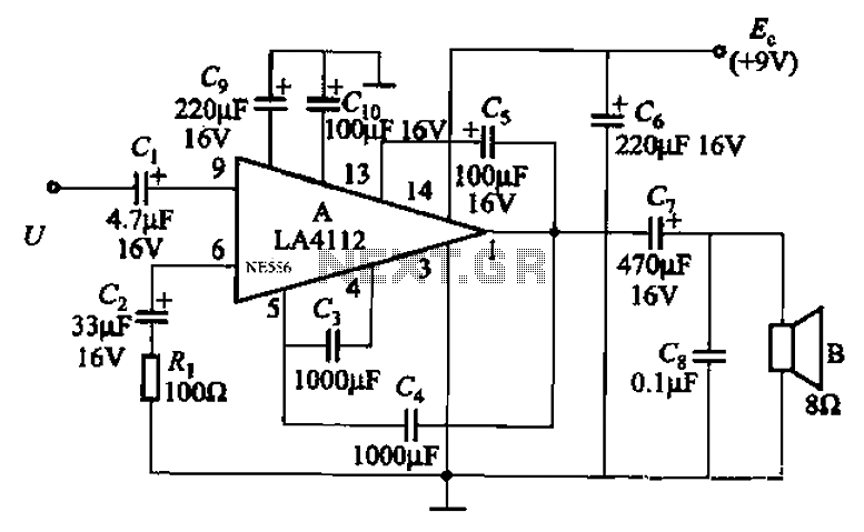
Audio power amplifier circuit utilizing the LA4112 integrated power amplifier along with additional components as shown in the figure. The audio power amplifier circuit based on the LA4112 integrated power amplifier is designed to deliver high-quality audio amplification for various...
With the help of a simple ceramic piezoelectric detector, it is possible to assemble an interesting and useful impact sensor unit, which can be used to detect... An impact sensor unit utilizing a ceramic piezoelectric detector operates by converting mechanical...
After several days of considering electronic fuel injection for a moped, a decision has been made to proceed with the project. The required parts have been identified, and the remaining task involves programming. The implementation of electronic fuel injection (EFI)...