
USB Single Cell Charger

You can select between 4.1V and 4.2V battery regulation point;
You can select between 100mA and 500mA current drain from USB.
The Maxim MAX1811 is a highly efficient integrated circuit designed specifically for charging single-cell Lithium Polymer (LiPo) batteries. This IC is particularly beneficial for portable electronic devices due to its ability to operate directly from a USB power source or an external supply voltage ranging from 4.5V to 6.5V. The MAX1811 is housed in a compact SO-8 package, facilitating easy integration into various electronic designs.
The primary function of the MAX1811 is to manage the charging process of LiPo batteries, which requires precise voltage and current control to ensure safety and longevity of the battery. The IC allows for the selection of two battery regulation voltages: 4.1V and 4.2V. This feature is crucial as it accommodates different battery chemistries and specifications, providing flexibility for designers.
Additionally, the MAX1811 offers a choice between two charging currents, 100mA and 500mA. This selection can be made depending on the application’s power requirements and the desired charging speed. The ability to adjust the charging current is particularly useful in scenarios where the USB power supply may be limited or where faster charging is necessary.
The design of the charger circuit using the MAX1811 typically includes several external components such as input and output capacitors, a sense resistor for current measurement, and a few passive components to support the operation of the IC. The overall circuit design ensures that the charging process is efficient, minimizes heat generation, and adheres to the safety standards required for LiPo battery charging.
In summary, the MAX1811 is an excellent choice for DIY projects involving Lithium Polymer batteries, providing essential features for safe and efficient charging while being easy to implement in various electronic designs.Lithium Polymer Batteries are a very common source of power today. Many electronics gadgets have one inside, and they have some reasonable features. I've bought great batteries, with different sizes and capacities for my electronics projects. So long I'm using this batteries, coming the problem: charge them. So, we start to find the correct circuit for my DIY charger. After some Google research I found the Maxim MAX1811 IC. It's a single-cell Lithium battery charger that can be powered directly from a USB or from an external supply up to 6.5V. It's use a SO-8 Package, easy to solder and can be sampled at Maxim. Other chip features are: You can select between 4.1V and 4.2V battery regulation point; ? You can select between 100mA and 500mA current drain from USB. 🔗 External reference
Related Circuits
The general principle is that reading prepares an individual, writing fosters daily improvement, and practice leads to perfection. Merely having theoretical knowledge is insufficient for an Electronics and Communication Engineering (ECE) student. A project entails developing hardware alongside software,...
Using only a single transistor and a few passive components, a fairly sensitive peak detector circuit can be built. This peak detector circuit is suitable for various applications. The peak detector circuit utilizes a single transistor, typically configured in a...
A battery is a vital element of any battery-backed system. In many cases, the battery is more expensive than the system it is backing up. Hence, practical measures must be adopted to conserve battery life. As per manufacturer's data...
In appliances that require alternating current, NiCad (NiCd) rechargeable batteries still demonstrate significant performance advantages compared to NiMH and lithium batteries. The charger circuit is critical in handling incorrect polarity of the battery placement. The core of this battery...
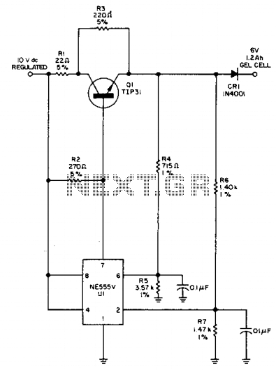
This circuit detects a full-charge state and automatically switches to a float condition—from 240 mA to 12 mA. The circuit uses the 555 timer. The described circuit is designed to monitor the charging state of a battery and to transition...
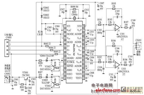
The peripheral circuit is straightforward, consisting of a DAC schematic circuit diagram for a USB interface that utilizes the PCM2702. The output of the circuit can be directly connected to a power amplifier and is capable of driving headphones...