
Using LEDs as colour sensors

The circuit operates by utilizing a reversed LED as a light sensor, which generates a small analog voltage proportional to the intensity of light it receives. This analog signal is then processed by an operational amplifier (op-amp) configured to amplify the signal to a suitable level for digital conversion. The op-amp's gain can be adjusted to ensure that the output voltage is within the acceptable range for the subsequent digital processing stage.
The digital conversion is achieved through a comparator circuit, which compares the amplified analog signal against a predefined threshold voltage. When the analog signal exceeds this threshold, the comparator outputs a high digital signal (logic '1'); otherwise, it outputs a low digital signal (logic '0'). This on/off output can be used for various applications, such as triggering a microcontroller or activating other digital logic circuits.
The modified schematic simplifies the original design by reducing the number of components and focusing on the essential functions required for analog-to-digital conversion. This streamlined approach enhances reliability and efficiency, making it more suitable for practical applications.
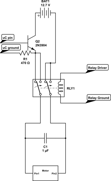
The hesitation to use the LED as a color sensor stems from previous testing results that may not have met the desired performance criteria. Alternative sensing methods or components might be considered to achieve more accurate color detection, such as photodiodes or specialized color sensors that offer improved sensitivity and spectral response.Part of this circuit is turning the analog signal coming from the reversed LED (sensing mode) and amplified by the op amp into a digital (on/off) signal. I got rid of all that. This is the modified simplified version of the schematics: Another possibility is the one explored in this tutorial but given my results so far I`m discouraged to use LED as colour sensors:
🔗 External reference
Related Circuits
This circuit is a simple 12V DC to 220V AC inverter that produces an AC output at line frequency, specifically 220V AC, or other voltages by selecting transformer T1. The 555 integrated circuit (IC) is configured as a low-frequency...
Many analog ohm meters have a non-linear scale, which results in poorer resolution at higher resistance values. This is due to the use of inexpensive current sources. Many analog ohm meters operate on a principle where the scale is not...
Capacitive sensors are utilized in various devices, ranging from consumer electronics to industrial and process control systems. Touch buttons are increasingly integrated into lamps and dimmers, while motion detectors can sense minute changes in deflection. Hygrometers measure humidity levels,...
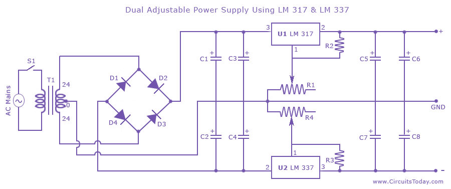
Dual adjustable power supply circuit with a diagram using IC LM317 and LM337. This variable power supply circuit has a range of 1.2 volts to 30 volts. The dual adjustable power supply circuit utilizes the LM317 and LM337 voltage regulators...
Control the state (on/off) and direction of two linear actuators that are essentially DC motors. The linear actuators operate at 12VDC and draw 10 amps of current at full load. A 25A external power supply has been purchased, as...
The LM383 schematic represents an 8-watt audio amplifier, which is straightforward to construct as a mini-audio power amplifier. The parts list includes the following components: C1 - 1 unit of a 10µF electrolytic capacitor, C2 - 1 unit of...