
valentines day gift

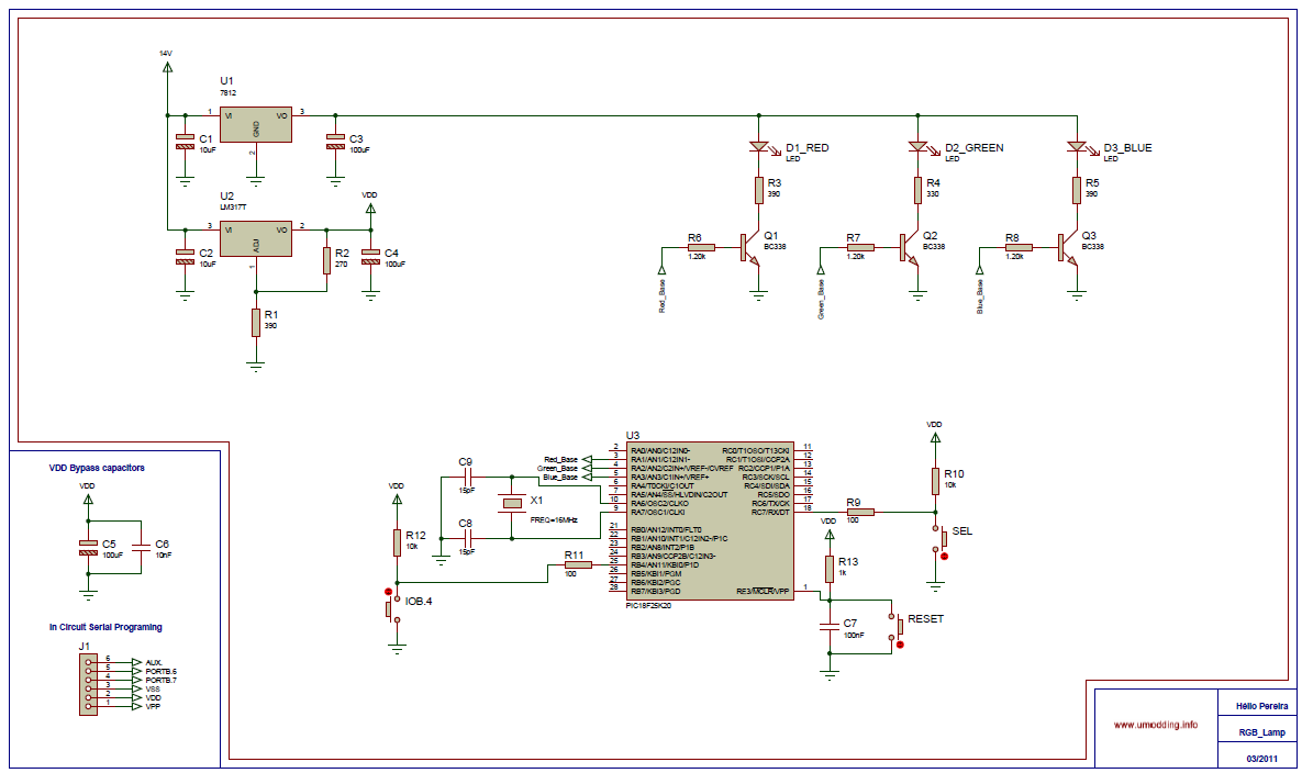
The circuit design for the throbbing LED heart employs a 555 timer configured in astable mode, which generates a continuous square wave output. This output is responsible for the pulsing effect of the LEDs. The duty cycle of the 555 timer can be adjusted by varying the resistor and capacitor values, allowing for control over the speed and intensity of the LED throbbing effect.
The NPN transistor serves as a switch, amplifying the current from the 555 timer to drive the 12 LEDs. In this configuration, the base of the NPN transistor is connected to the output of the 555 timer, while the collector is connected to the LED array. The emitter is grounded. When the output from the 555 timer goes high, the transistor turns on, allowing current to flow through the LEDs, illuminating them.
The capacitor in the circuit helps to stabilize the power supply and smooth out any fluctuations, ensuring consistent LED performance. The two resistors are used to limit the current flowing through the LEDs and the base of the transistor, preventing damage to the components.
In the schematic, six LEDs are shown in parallel, but it is essential to expand this to include all 12 LEDs as intended. Each LED in the parallel configuration should have its own current-limiting resistor to ensure even brightness and prevent any single LED from drawing too much current. The total forward voltage drop of the LED array must be considered when selecting the power supply to ensure adequate voltage and current are supplied to the circuit.
This design not only creates a visually appealing display for Valentine's Day but also serves as an excellent introduction to basic electronics concepts such as timing circuits, transistor switching, and LED operation.This year for Valentine`s Day I decided to get nerdy and make something electronic for Caroline. I first tried to make a animated LED heart with a joule thief and a single AA battery, but I couldn`t make a suitable air coil. So, I decided to modify this circuit to make a throbbing LED heart. The circuit uses a 555 timer, NPN transistor, 12 LEDs , a capacitor, and two resistors. The schematic is below. I only drew in 6 LEDs in parallel, but there should be 12. 🔗 External reference
Related Circuits
The Circuit is composed of two sections, the light sensing and the power switching. The light sensing part consists of a photo-resistor R4, connected like a voltage divider to R2. Since the resistance of the photo-resistor changes depending on...
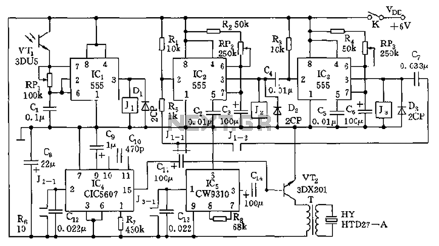
The circuit consists of four light-controlled electronic switches, timing circuits, voice circuits, audio circuits, and other components. It is designed to celebrate birthdays or similar occasions, with features such as birthday candles that can be lit or extinguished. The...
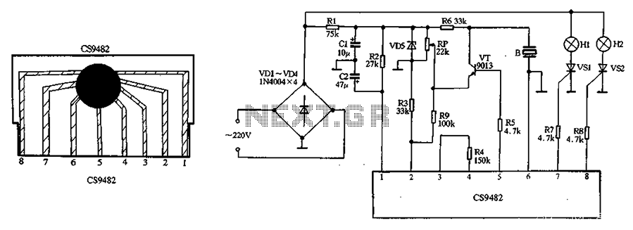
The CS9482 integrated circuit fabrication is demonstrated with a holiday lights circuit. The CS9482 chip includes a 4.1V voltage regulator circuit; therefore, while the external circuit does not need to be regulated, if the voltage exceeds 4V, a current-limiting...
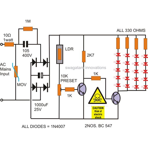
The power supply utilized in this circuit is of the capacitive type, eliminating the need for a transformer and allowing for a compact design that can be easily installed in small spaces. The circuit employs LEDs instead of traditional...
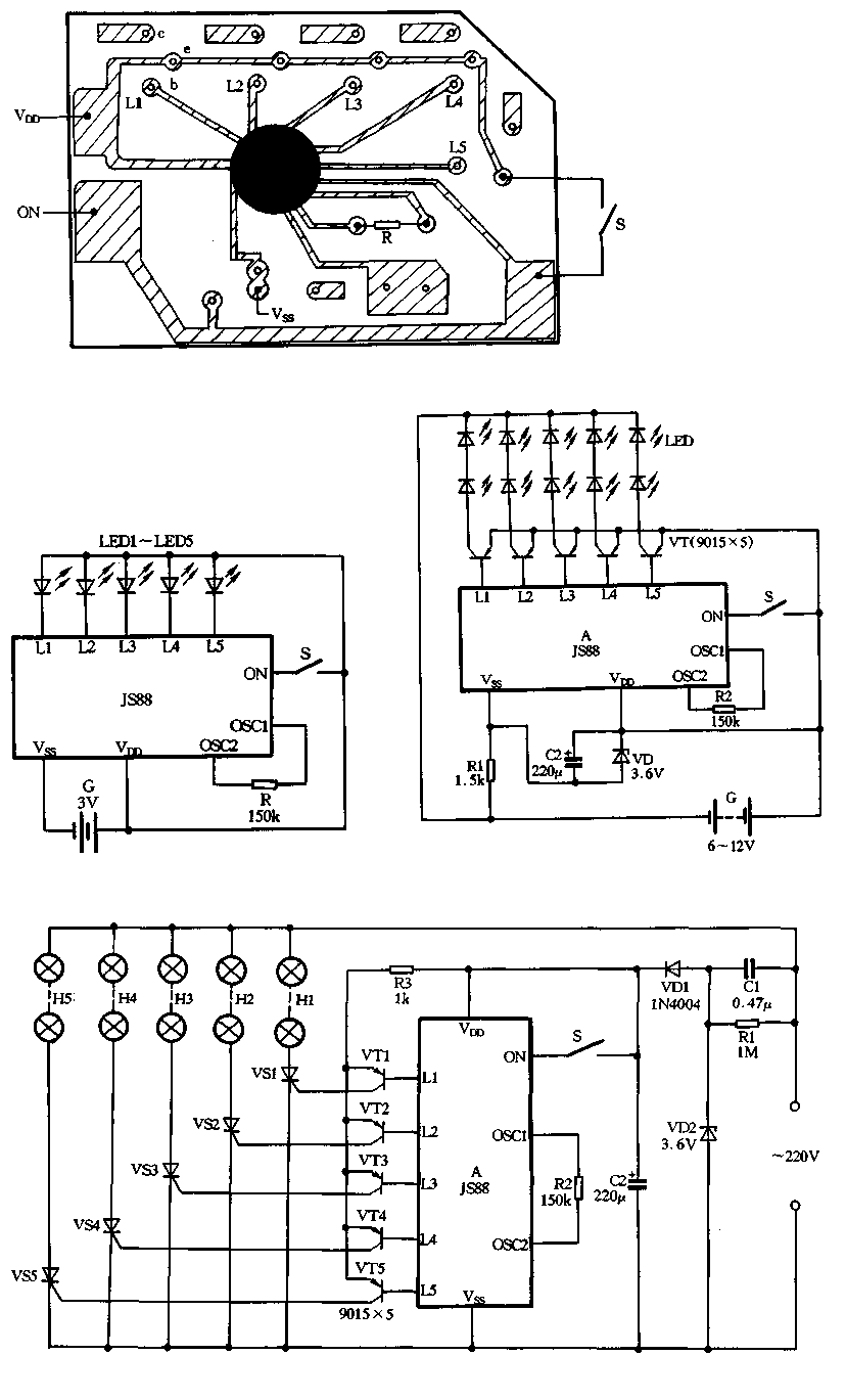
Figure 2-39 illustrates a typical application circuit for the JS88 manifold, which includes an oscillation resistor (R) that allows for fine-tuning of the water flicker frequency. When switch (S) is closed, components L1 to L5 sequentially output low signals...

The TN-1 Intelligent Negative Pulse Charging Circuit is a sophisticated device designed for efficient battery charging. It operates as a half-bridge charger, which is a common configuration in such circuits. The negative pulse charging mechanism is facilitated by a...