
Varactor The Core of Voltage Controlled LC Tuner

In hybrid systems, the integration of analog and digital components allows for enhanced functionality and versatility in various applications. The voltage-controlled elements serve as a bridge between the digital and analog domains, enabling precise control over analog signals. The DAC plays a pivotal role in this setup by converting digital signals into corresponding analog voltages, which can then be used to control various analog devices, such as motors, sensors, and amplifiers.
The design of such a hybrid system typically involves several key components: the digital control unit, the DAC, and the analog subsystems. The digital control unit, often implemented using microcontrollers or digital signal processors (DSPs), generates the digital signals based on the desired output or control parameters. These digital signals are then fed into the DAC, which converts them into analog voltages. The output voltage of the DAC can be adjusted based on the input digital values, allowing for fine-tuned control over the connected analog devices.
Additionally, feedback mechanisms may be incorporated to monitor the performance of the analog components. Sensors can be used to provide real-time data to the digital control unit, enabling dynamic adjustments to the output voltage as needed. This feedback loop enhances the system's responsiveness and accuracy, making it suitable for applications such as robotics, automated control systems, and audio processing.
Overall, the combination of analog systems with digital control through voltage-controlled components and DACs is fundamental in creating efficient, high-performance hybrid systems that meet the demands of modern electronic applications.In hybrid system, analog system with digital control, a voltage controlled things is very important since it can be interfaced by DAC from digital system. For.. 🔗 External reference
Related Circuits
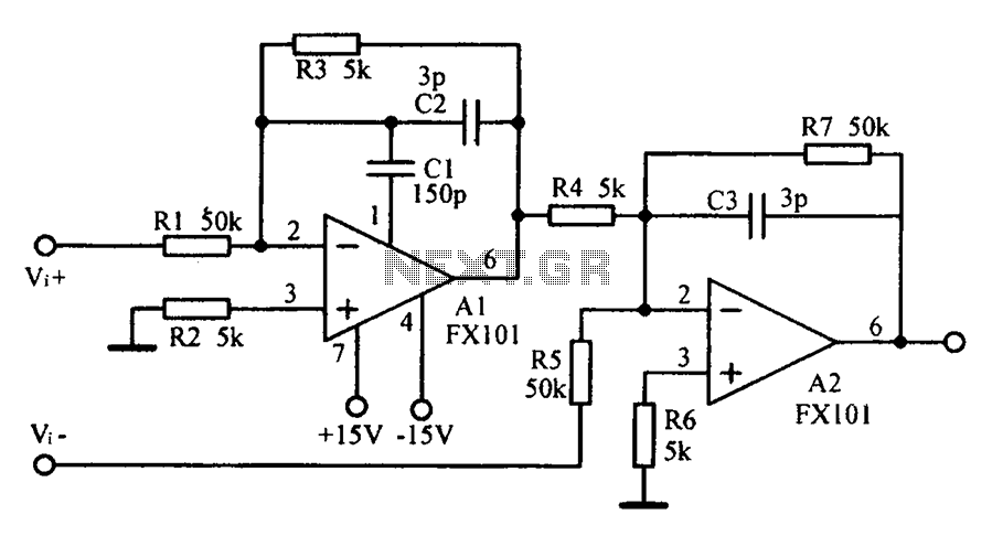
Common mode input voltage up to a difference of 100V enlarged circuit diagram. The circuit diagram described features a design capable of handling a common mode input voltage with a differential range of up to 100V. Such a configuration is...
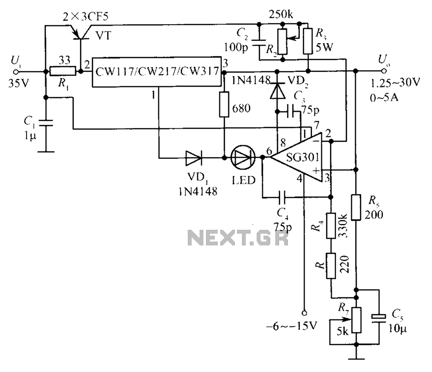
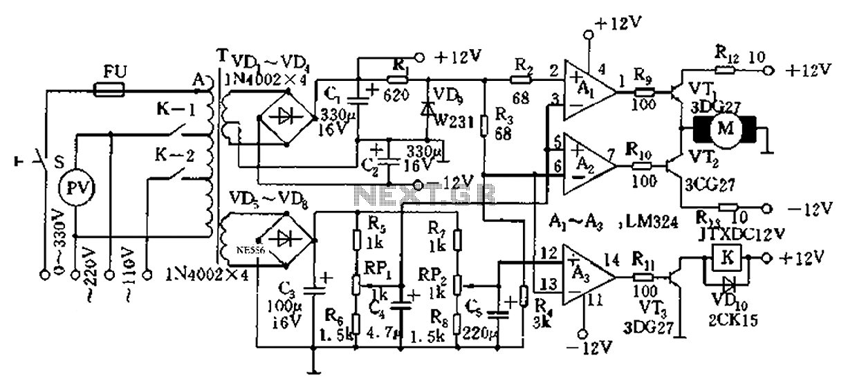
This document presents a diagram of a constant voltage/current power supply box. It is composed of three main components: spread current, constant voltage, and constant current. The design features two 3CF5 power transistors arranged in parallel, functioning as an...
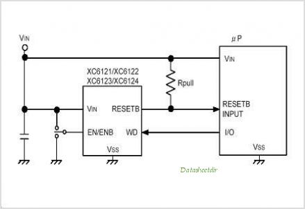
The XC61H series is a highly accurate, low power consumption CMOS voltage detector featuring a delay circuit. The detection voltage maintains high accuracy with minimal temperature drift. Output configurations are available in both CMOS and N-channel open drain. As...
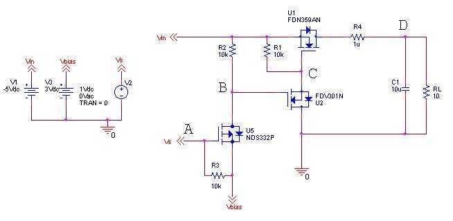
The idea is simply to turn off the negative voltage load. Some examples: - Bias voltages for LCD panels - RF Amplifiers - Audio Amplifiers The good thing about this design is that I can make use of the system...
Automatic AC voltage regulator circuit TXD1742 with continuous adjustment. The TXD1742 is an automatic AC voltage regulator circuit designed to provide continuous voltage adjustment, ensuring stable output voltage in varying load conditions. This circuit is particularly useful in applications where...
The under/over voltage protection circuit with time delay presented here is a low-cost and reliable circuit for protecting equipment from damage. This under/over voltage protection circuit is designed to safeguard electronic equipment from voltage fluctuations that can lead to potential...