
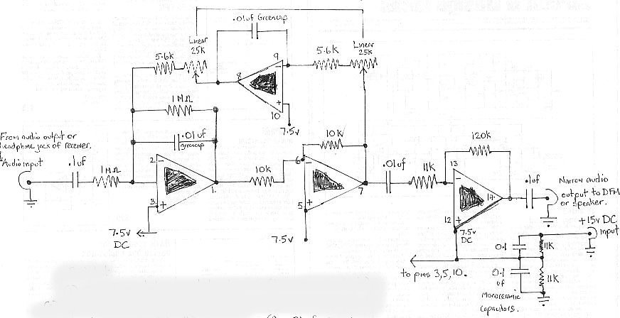
Variable bandwidth bandpass active filter

The circuit operates around a central frequency of 800 Hz, which is essential for applications requiring precise frequency selection and filtering. The use of a 10 kΩ potentiometer allows for fine-tuning of the bandwidth, providing flexibility in signal processing. The bandwidth adjustment range is significant, spanning ±350 Hz to ±140 Hz, which corresponds to the 3 dB down points of the frequency response curve.
In practical terms, this means that the circuit can effectively filter signals within a range of frequencies centered around 800 Hz. When the bandwidth is set to its maximum of ±350 Hz, the circuit can accommodate a broader range of input signals, making it suitable for applications where signal variability is expected. Conversely, narrowing the bandwidth to ±140 Hz allows for more selective filtering, which is advantageous in scenarios where precision is critical, such as in audio processing or communication systems.
The design may incorporate operational amplifiers or active filters to achieve the desired frequency response characteristics. By adjusting the potentiometer, the user can modify the gain and phase response of the circuit, thereby tailoring the performance to specific requirements. The circuit's ability to adjust bandwidth dynamically makes it a versatile component in various electronic systems, enhancing its applicability in both consumer and professional audio equipment.This circuit has adjustable bandwidth with values for a center frequency of about 800 Hz The 10-K pot adjusts bandwidth from approximately ±350 Hz to ±140 Hz at 3 dB down points.
Related Circuits

The circuit comprises three stages. The first stage includes a transformer, a bridge rectifier, and a 10,000 µF electrolytic capacitor, which serve to isolate and reduce the voltage while improving and filtering the output. The second stage consists of...
R2 sets the output voltage. The maximum current is determined by the value of R3: the over-current protection circuitry inside the LM723 senses the voltage across R3 and starts shutting the output stage off as soon as this voltage...
The second-order multipurpose filter described here can function as a low-pass, bandpass, high-pass, or notch filter at audio frequencies. Its unique feature is the ability to independently vary all characteristics using potentiometers. In basic filters, only one k value...
The audio bandpass filter described is beneficial for amplifying and filtering weak AM TV video carriers. For instance, a digital frequency audio multimeter (DFM) may lack sufficient input sensitivity for measuring extremely weak single sideband (SSB) TV video audio...
This audio noise filter circuit is a bandpass filter designed for the audio frequency range. It effectively filters out unwanted signals that fall outside the audio frequencies. The circuit consists of two filters: a low-pass filter and a high-pass...
This circuit illustrates both sections of an LM833 configured as a filter to eliminate unwanted ultrasonic signals. The filter exhibits a 4th-order Bessel characteristic, with a -3 dB frequency approximately at 40 kHz. It is recommended that resistors and...