
Second-Order Audio Filter Performs Multiple Functions

The second-order multipurpose filter is designed to operate effectively at audio frequencies, allowing for versatile applications in audio signal processing. The circuit topology utilizes operational amplifiers (op-amps) to achieve the desired filtering characteristics. The filter can be configured for various modes, such as low-pass, bandpass, high-pass, and notch filtering, depending on the application requirements.
The independent adjustment of filter parameters is facilitated through the use of potentiometers, which provide flexibility in tuning the filter's response. The resistors R1 and R2 are critical for determining the characteristic frequency, while R6 is specifically designated for modifying the Q value, which affects the selectivity and bandwidth of the filter. The gain of the filter can be adjusted using R5, impacting the output amplitude without altering the filter's frequency characteristics.
The circuit's outputs, marked as LP, HP, and BP, allow users to select the desired filter response based on the application. The ability to derive additional filter types through linear combinations enhances the circuit's versatility, making it suitable for a wide range of audio processing tasks. The inclusion of dual potentiometers ensures that adjustments can be made smoothly and efficiently, maintaining the integrity of the filter's performance.
Furthermore, the implementation of a linear combination filter, as illustrated in Figure 4, expands the circuit's functionality by allowing for the integration of multiple filter responses. This capability is particularly valuable in complex audio systems where specific filtering requirements must be met. Each input's variable voltage gain provides additional control over the signal processing, enabling precise manipulation of audio signals to achieve the desired sound quality.
Overall, this second-order multipurpose filter represents a sophisticated solution for audio frequency filtering, combining flexibility, independence of adjustments, and the potential for complex filter designs.The second-order multipurpose filter described here can perform as a low-pass, bandpass, high-pass, or notch filter at audio frequencies. What makes this filter unique is that all of its characteristics can be varied independently with potentiometers.
In basic filters, only one k value is non-zero. Figure 1`s circuit includes the three basic types of filters. The characteristic frequency, Q value, and transfer gains are: When resistors R3, R4, and R8 have the same value, the parenthetical expressions are valid. R1 and R2 cause the characteristic frequency to change independently. To independently vary the Q value, R6 is adjusted. All of the gains change when R5 is modified. There are three useful outputs in the circuits. They are low-pass, high-pass, and bandpass outputs. In the circuit diagram, these are marked with abbreviations LP, HP, and BP. Replacing resistor R5 with the circuit in Figure 2 makes the gain adjustable. This method can also be used with the Q value. It`s possible to achieve adjustability by replacing resistor R6 with Figure 2`s circuit. The characteristic frequency adjustment is more complicated. To keep the adjustments independent, resistors R1 and R2 should be adjusted at the same time. This can be accomplished using the dual potentiometer as demonstrated in Figure 3. Although the pots are linear, the adjustment is logarithmic due to the virtual ground at the op amp`s negative input.
The component values are selected so that the characteristics dependent on the potentiometer rotation follow Table 1. It must be emphasized that all the adjustments are independent. Gain adjustment has no effect on Q value or frequency. This is true for the Q value and characteristic frequency adjustments as well. There are several other types of filters that can be derived using this basic configuration. All can be made using linear combinations of the three basic filters, as summarized in Table 2. Figure 4 illustrates a circuit that can be used to implement the linear combination filter. It allows both polarities, and each of its inputs has a variable voltage gain from 0 to 1. 🔗 External reference
Related Circuits
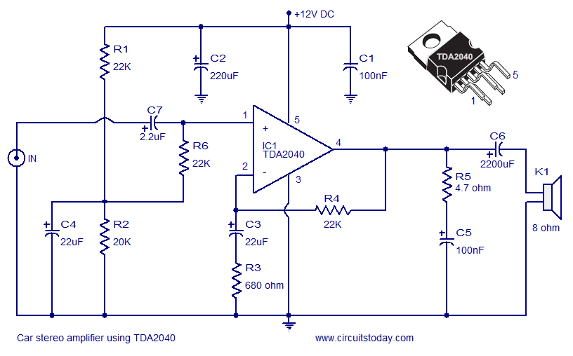
A car stereo amplifier circuit utilizing the TDA2040 is presented here. The TDA2040 is a monolithic integrated audio amplifier that functions in Class AB mode. This integrated circuit features built-in short circuit protection and thermal shutdown capabilities, and it...
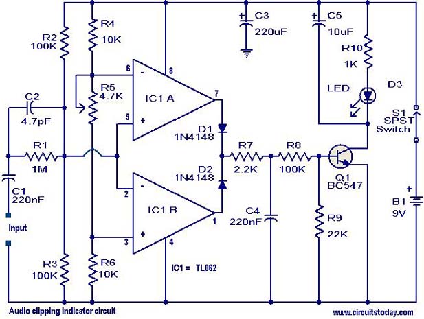
This circuit is designed to detect clipping in a specific waveform. Clipping occurs when the amplitude of a waveform decreases before reaching its expected limit. The circuit activates an LED as an indication that the tested signal is experiencing...
Application circuit using three stereo digital potentiometers to control volume, balance, and fader in a four-speaker configuration with a push-button interface. The application circuit utilizes three stereo digital potentiometers, which are essential components for managing audio levels in a multi-speaker...
If you want to build one yourself, you have to get two audio transformers which have 1:1 transformation ratio and greater than 1 kohm impedance. There are high quality audio transformers in the markets that meet those specs, but...
The lf555afosc1.pdf file download contains a diagram with annotations for a Sub-Tone (CTCSS or "PL") Oscillator, designed using the well-known 555 timer IC configured for astable multivibrator operation. The component values are selected to position the tone range near...
This audio mixer circuit schematic is designed around four current-controlled amplifiers, all integrated within the SSM2024 IC. The audio mixer circuit utilizes the SSM2024 integrated circuit, which features low-noise, high-performance operational amplifiers suitable for audio applications. The SSM2024 is particularly...