
Variable DC Power Supply

The LM317 is a popular adjustable voltage regulator that can deliver a stable output voltage with high precision. In this configuration, the regulator is set to accept a DC input voltage of approximately 28 volts, which is necessary for proper operation. The output voltage can be adjusted between 1.25 volts and 25 volts, making this circuit suitable for a variety of applications requiring different voltage levels.
The adjustment of the output voltage is accomplished using a 5k ohm potentiometer. This potentiometer is connected in a voltage divider configuration with two resistors, allowing for fine-tuning of the output voltage as needed. The output voltage is determined by the formula:
\[ V_{out} = V_{ref} \left(1 + \frac{R2}{R1}\right) + I_{adj} \cdot R2 \]
where \( V_{ref} \) is typically 1.25 volts, \( R1 \) is the resistor connected between the output and the adjustment pin, and \( R2 \) is the potentiometer connected from the adjustment pin to ground. The adjustment pin also allows for minor current adjustments, but this is generally negligible in most applications.
The LM317 can supply up to 1.5 amps of current, which makes it suitable for powering various electronic devices and circuits. To ensure reliable operation, proper heat sinking is recommended, especially when the input voltage is significantly higher than the output voltage, as this can generate considerable heat within the regulator.
In summary, this circuit provides a versatile and adjustable power supply solution, leveraging the capabilities of the LM317 to deliver a wide range of output voltages while ensuring stable performance under varying load conditions. Proper component selection and layout are essential for optimizing the performance and reliability of this power supply design.This power supply is based on the LM317 Variable Regulator. The input of the regulator needs to be around 28 Volts DC and it will output a DC voltage from 1.25vdc to 25 vdc. To adjust the output voltage simply turn the 5k ohm pot. The regulator will supply 1.5 amps of current. 🔗 External reference
Related Circuits
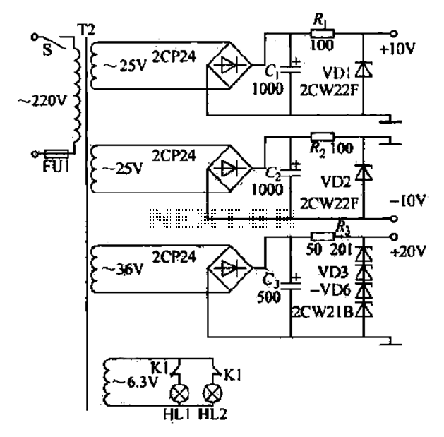
DC power supply with a shunt, rectifier, filter, limiter, and regulator. The circuit is simple and cost-effective, capable of meeting the requirements. The 6.3V indicator lights HL1 and HL2 indicate the lathe's running and stopping status through a relay...
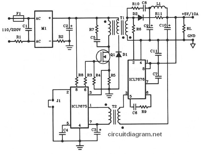
The following diagram illustrates the design of a 50W offline switching power supply circuit. This circuit is powered by a MOSFET, specifically the BUZ80A/IXTP4N8 for 220V AC input and the GE IRF823 for 110V AC input voltage. The output...
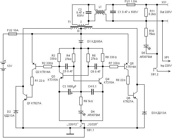
220 watts Uninterruptible Power Supply. Refer to the designated page for an explanation of the related circuit diagram for this power supply. The 220 watts Uninterruptible Power Supply (UPS) is designed to provide reliable backup power during outages, ensuring that...
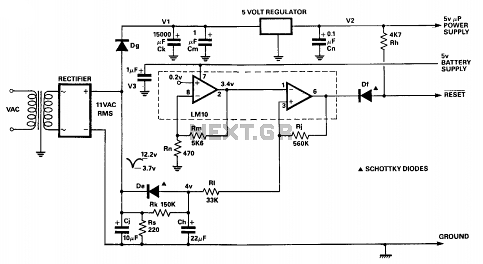
The circuit monitors the input to the microprocessor's 5 V regulated supply for voltage drops and initiates a reset sequence before supply regulation is lost. In operation, the resistor-capacitor combination Rs and Cj forms a short time constant smoothing...
The following circuit diagram depicts a variable power supply controlled by a PIC microcontroller. An LCD display is utilized to show the actual output current and voltage values. This digital power supply incorporates a push-button switch to adjust the...
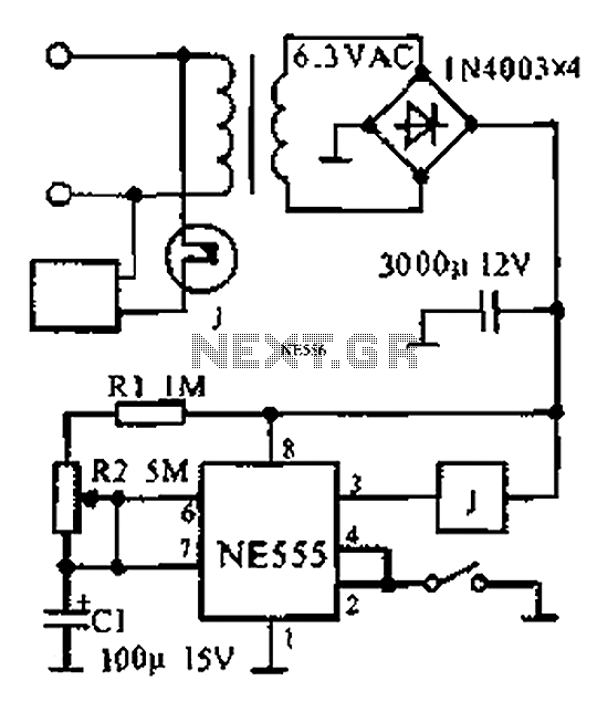
The provided information indicates that when the power supply operates between 0 to 1 hour, an AC circuit diagram is established using a 555 timer configured as a one-hour timer. The relay utilized is a J 212 IRC MR312C...