
Vcr Tv On-Off Control Circuit

The circuit design employs an operational amplifier (U3A) configured as a signal amplifier to boost the video signal from the VCR. The amplified output from U3A is then fed into a transistor (Q1), which acts as a switch. When the VCR is activated, the operational amplifier detects the presence of the video signal and triggers Q1 to conduct. This, in turn, activates a relay (K1) or a similar switching device, allowing the downstream video device to receive the amplified signal without manual intervention.
The advantages of this configuration include simplified operation for the user, as it automates the switching process between devices, ensuring that the video signal is consistently routed to the appropriate output without requiring additional steps. Additionally, this circuit can enhance the overall reliability of the video system by minimizing the wear and tear associated with frequently toggling power states on multiple devices.
Furthermore, the design can be optimized by incorporating features such as signal conditioning to filter out noise, ensuring a clean video output. Protection components, such as diodes, can be added to safeguard against voltage spikes that may occur when switching states, thereby increasing the longevity and robustness of the circuit.
In summary, this circuit effectively streamlines the operation of a video system by automating the signal detection and switching process, reducing the need for manual intervention, and enhancing the overall user experience. This circuit senses the video from the VCR. When the VCR is turned on, video signal is amplified by U3A and to drive Ql, activating Kl. In this manner, it is not necessary to turn on and off two video devices every time. In many cases, this avoids the use of a cable box, the cable-ready VCR performing this function.
Related Circuits
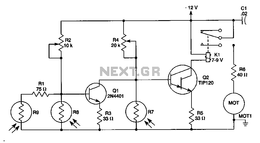
The sun trucker employs three photoresistors, R7, R8, and R9, to enable the circuit to track the sun during daylight hours while ceasing operation at night. Additionally, the circuit can be duplicated to achieve movement along four axes by...
This is a straightforward infrared detector circuit designed to detect infrared light. The circuit comprises only three components: an RS-276-145 photo transistor, a 330-ohm resistor, and a general-purpose LED (Light Emitting Diode). When the photo transistor receives infrared light...
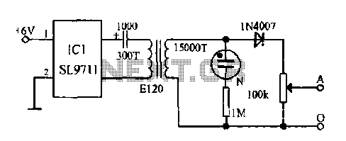
The electronic frostbite treatment instrument ASIC SL9711 consists of an oscillation circuit, a power amplifier, and a controller. It generates a sine wave at frequencies of 100 Hz and 3 Hz, followed by a step-up transformer with potentiometer adjustment...
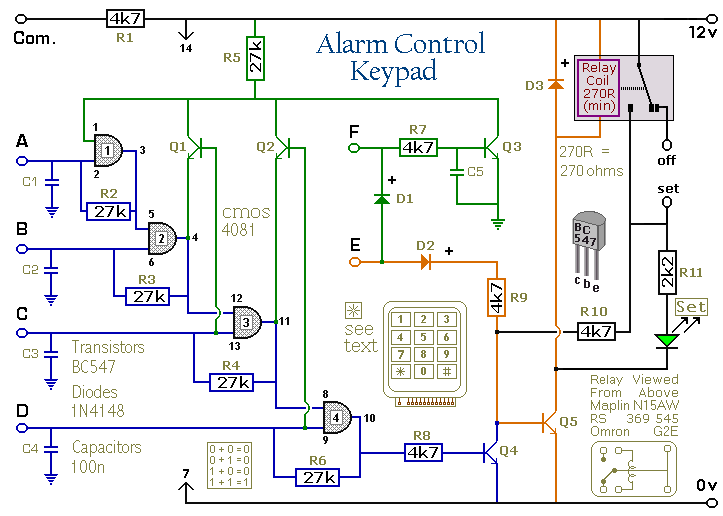
Pressing a single key on the keypad energizes the relay. Entering a four-digit code of your choice de-energizes the relay. The circuit was designed to control the Modular Burglar Alarm System but can have other applications. A five-digit version...
Unlike LED light, a laser's light output is more concentrated, resulting in a smaller and narrower viewing angle. This characteristic necessitates that the laser light be directed more precisely at its source for effective detection. Laser light is also...

This circuit is similar to the one found in the Single Buss 1V/Octave Keyboard Controller. Refer to the circuit description there for more details. This board includes additional resistors used in the keyboard voltage divider. In a typical keyboard,...