
How To Build A Simple Alarm Control Keypad

The described circuit operates as a simple yet effective security mechanism utilizing a keypad to control a relay, which in turn can activate or deactivate a modular burglar alarm system. The design emphasizes user interaction through a straightforward four-digit code entry system, ensuring ease of use while maintaining security. The relay's operation is contingent upon the correct sequence of key presses, with a specific key designated to initiate the activation process (terminal "E").
To enhance functionality, the circuit allows for a customizable security code by permitting users to choose any four keys from the keypad for the deactivation process. This flexibility is crucial for adapting the system to different user preferences or security needs. The use of a common terminal for the keypad simplifies wiring and reduces potential errors during assembly, while the requirement for 13 terminals ensures compatibility with standard 12-key keypads.
The visual feedback provided by the green LED is an important feature, as it informs users of the system's status—activated or deactivated. This indicator serves as a deterrent to potential intruders, as it clearly shows whether the alarm is armed. The inclusion of incorrect key handling—where pressing any key not designated for the code resets the sequence—adds an additional layer of security, preventing unauthorized attempts to gain access.
For users seeking heightened security, the option to utilize a five-digit code or a larger 16-key keypad expands the number of possible combinations exponentially. This scalability makes the circuit suitable for various applications beyond just burglar alarms, including access control systems or other security-related uses. The comprehensive support materials provided ensure that users can successfully construct and implement the circuit, making it accessible even to those with limited electronics experience.Pressing a single key on the keypad - will energize the relay. Entering a four-digit code of your choice - will de-energize the relay. The circuit was designed to control the Modular Burglar Alarm System - but it will have other applications. If you require added security - A Five-Digit Version - of the circuit is also available. The Keypad must b e the kind with one common terminal - and a separate connection for each key. On a 12-key pad - look for 13 terminals. The matrix type with 7 or 8 terminals will NOT do. On the Support Page you`ll find details of how to Make Your Own Keypad. The relay is energized by pressing a single key. Choose the key you want to use - and connect it to terminal "E". Choose the four keys you want to use for your security code - and connect them to "A B C & D". Wire the common lead to R1- and all the remaining keys to "F". When you press "E" the relay energizes - and the 12-volt output moves from the "off" to the "set" terminal. The green LED also lights. It provides a visual indication that the alarm is set. When you press keys "A B C & D" in the right order - the relay de-energizes - and the 12-volt output returns to the "off" terminal.
The green LED is also extinguished - to indicate that the alarm is switched off. The remaining keys - those not wired to "A B C D & E" - are connected to "F". Whenever one of these "Wrong" keys is pressed - the attempted code entry fails - and the code entry sequence is reset. The same thing happens if "C" or "D" is pressed out of sequence. If "C" is pressed before "B" - or "D" is pressed before "C" - the attempted code entry will fail. And the code entry sequence will reset. With a 12-key pad - over 10 000 different codes are available. If you need a more secure code - you could simply use a bigger keypad with more "Wrong" keys wired to "F".
A 16-key pad gives over 40 000 different codes. If you make a mistake while entering the code - simply start again. The Support Material for this circuit includes a step-by-step guide to the construction of the circuit board - a parts list - a detailed circuit description - and more. 🔗 External reference
Related Circuits
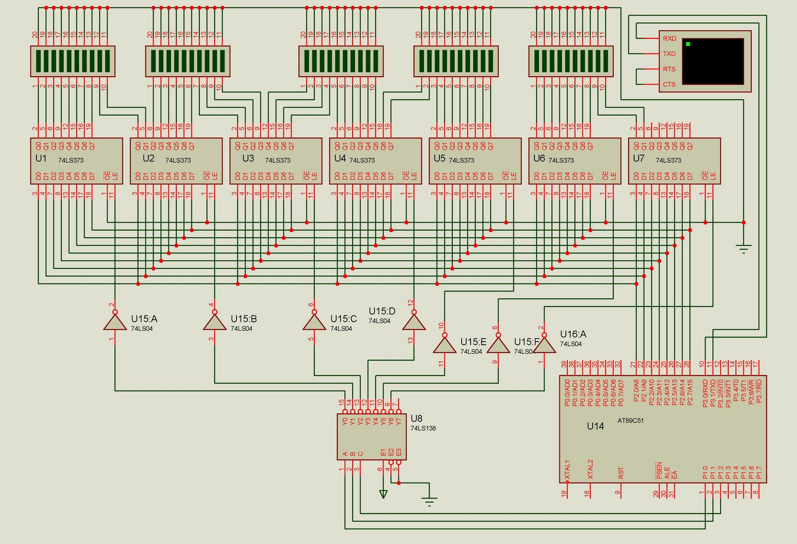
This project is designed to control up to 50 solid-state relays independently. It serves as an excellent learning resource for students who wish to expand the input-output lines of a microcontroller and control multiple devices. The ON or OFF...
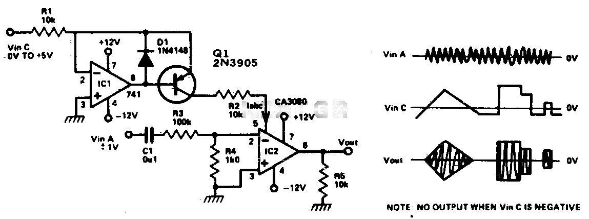
This circuit is essentially an operational amplifier (op-amp) with a differential input voltage of ±10 mV between pins 2 and 3, along with an additional input at pin 5. A current (Iabc) is injected to control the current at...
A real-time controller is a device designed to continuously manage household devices, both in real-time and according to a predetermined schedule. This article focuses on a series of real-time controllers utilizing the AT89C2051 microcontroller, which serves this purpose effectively....
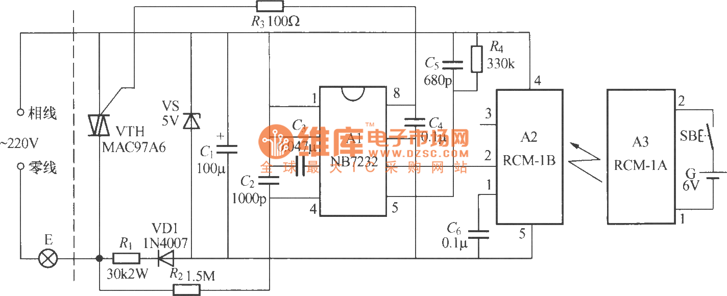
The diagram above illustrates a radio remote control dimmer circuit. This circuit utilizes a micro radio transmit/receive module in conjunction with a light modulation ASIC, resulting in a compact and easily producible design. It operates reliably and features a...
To sense and control the current in stepping motors and other similar devices, a linear integrated circuit such as the L6506 can be utilized. This chip set enables the formation of a constant current output. The L6506 is a versatile...

One-half of a 556 dual timer monitors the temperature of a liquid bath, controlling a heating element that maintains temperature within ±2°C over a 32° - 200°C range. The other half monitors the liquid level, disconnecting the heater when...