
Vehicle Accessory Computer Interface

The project is named SmartJeep and was authored by Marco van der Merwe. It is protected under copyright, with all rights reserved since its release on August 21, 2010. Version 1.0 serves as a test application for serial communications and RGB control.
The circuit utilizes the PIC16F877 microcontroller, which features a specific pinout for various functions such as MCLR, GPIO, and RS232 communication. The configuration includes setting the device to 16F877A with bootloader options enabled and high-speed oscillator settings using a 20MHz crystal. The serial port is configured for a baud rate of 9600, ensuring effective communication with external devices.
The software structure includes variable declarations for serial communication, RGB control, and adjustable settings for exterior and interior lighting. The use of interrupts is crucial for handling serial data reception, ensuring that the system remains responsive. The initialization of various parameters, including a delay for power stabilization, is essential for reliable operation. The TRIS registers are configured to set the direction of the GPIO pins for controlling RGB outputs.
This comprehensive design allows for the integration of various vehicle accessories, providing a flexible platform for customization and automation. The attention to detail in the circuit design and software implementation highlights the potential for creating an advanced vehicle accessory control system.The following document will provide information to develop your own VACI (Vehicle Accessory Computer Interface). What I have done is rather simple, however it took about 3 weeks of planning, programming and debugging.
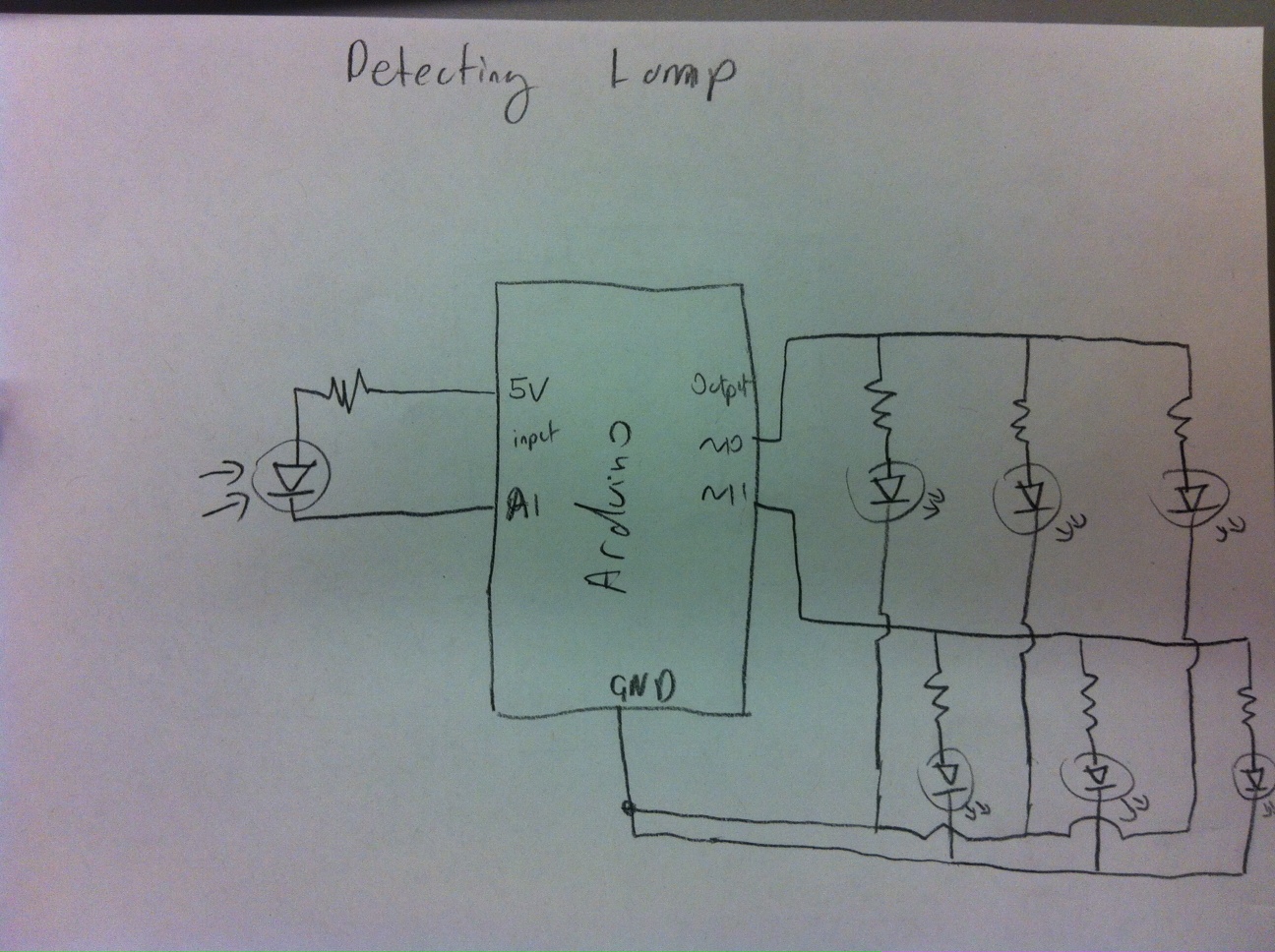
The wow factor on this interface is awesome; everyone that has seen/used the system wants one in their car. The system can also be modified to automate accessories. If you have an Olimex PIC-40 Development board, you shouldn`t need a schematic. If you don`t, then you only need to build a stable 5V regulator to power the circuit and a RS232 logic level converter so that you can connect the serial of your computer to the serial of the microcontroller. The other important thing is to have all your outputs connected to a ULN2803 Darlington Array IC and remember that the maximum load per output should not exceed 60mA.
The ULN2803 is a sinking driver, so you are able to drive your 12V relays from 12VDC. I have also uploaded the musltisim and ultiboard schematic and PCB design files, use them at your own risk. I have not tested the ultiboard design and will not accept any responsibility for it. In a nutshell, the RGB software PWM works through an infinite loop with a counter which resets after 255 (one Byte).
Each color byte is then compared to the clock, if it is less than the clock, the output is set high. If the color byte is greater than the clock byte, the output is set to low. The color bytes are then changed through a serial data received interrupt. `* `* Name : SmartJeep. BAS * `* Author : Marco van der Merwe * `* Notice : Copyright (c) 2010 * `* : All Rights Reserved * `* Date : 8/21/2010 * `* Version : 1. 0 * `* Notes : Test app for serial comms & RGB Controll * `* : * `* ` PIC16F877 Pinout ` - ` MCLR -|1 |_| 40|- ` AvSAT -|2 39|- ` AvDVD -|3 38|- Interior Blue ` AvCaTV -|4 37|- Interior Green ` AvVCR -|5 36|- Interior Red ` AvAux -|6 P 35|- Exterior Blue ` Av1/Av2 -|7 I 34|- Exterior Green ` Av PWR -|8 C 33|- Exterior Red ` -|9 1 32|- Vdd (5V) ` -|10 6 31|- Vss (0V) ` Vdd (5V) -|11 F 30|- GPIO 7 ` Vss(0V) -|12 8 29|- GPIO 6 ` Xtal(20Mhz) -|13 7 28|- GPIO 5 ` Xtal(20Mhz) -|14 7 27|- GPIO 4 ` -|15 A 26|- RS232(Rx) ` -|16 25|- RS232(Tx) ` -|17 24|- ` -|18 23|- ` GPIO 0 -|19 22|- GPIO 3 ` GPIO 1 -|20 21|- GPIO 2 ` - Device = 16F877A ` Select PIC16F877A for Destination Device Declare Bootloader = On ` Notify Compiler of Bootloader Config HS_OSC ` Make use of High Speed Oscilator Xtal = 20 ` Use 20Mhz Xtal Optimiser_Level = 1 ` Simple optimisation Dead_Code_Remove = On ` Remove any redundant code `Configure Hardware Serial Port Hserial_Baud = 9600 ` Set baud rate to 9600 Hserial_RCSTA = %10010000 ` Enable serial port and continuous receive Hserial_Clear = On ` Optionally clear the buffer before receiving `Disable Analog Ports All_Digital true `Serial Related Variables Dim D_Index As Byte ` Char Rx index Dim D_Byte[12] As Byte ` Rx buffer Symbol RCIF = PIR1.
5 ` Alias RCIF (USART Receive Interrupt Flag) `Switch Vars Dim AVclk As Byte Dim AVMode As Byte Dim GPO As Byte `RGB Variables Dim clk As Byte ` clk Counter `Adjustable Variables Dim ERGB[3] As Byte `Exterior Red, Green, Blue Dim EBSO[3] As Byte `Exterior Brightness, Speed, Option Dim IRGB[3] As Byte `Interior Red, Green, Blue Dim IBSO[3] As Byte `Interior Brightness, Speed, Option `Important Note: `EBSO & IBSO have not been fully implemented, `they are put in place to support RGB effects and transitions `- ` Initialise variables DelayMS 500 ` Wait for the power supply to stabilise INTCON = %11000000 ` Enable interrupts On_Hardware_Interrupt GoTo SerialIn ` Declare hardware interrupt handler routine PIE1. 5 = 1 ` Enable interrupt on USART D_Index = 0 ` Initialise index as 0 clk = 0 ` Initialise Clk as 0 AVclk = 0 ` Initialise AVclk as 0 AVMode = 0 ` Initialise AVMode as 0 GPO = 0 ` Initialise GPO as 0 TRISB = %11000000 ` Set 0~5 on PortB as output for R1G1B1 R2G2B1 TRISA = %11000000 ` Set 0~6 on Por
🔗 External reference
Related Circuits
A habit-acquisition system that tags physical objects, such as dumbbells and medicine bottles, with RF tags or microcontrollers to detect and log user interactions with these items. It includes virtual plants and creatures that simulate the health of real-world...
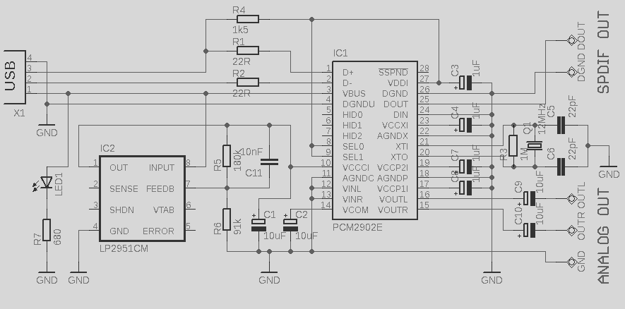
This circuit is a quality preamplifier with a built-in USB DAC designed for the Leachamp power amplifier. The schematic is based on the PCM2902 datasheet. The circuit includes a DAC and ADC, SPDIF input and output, and features three...
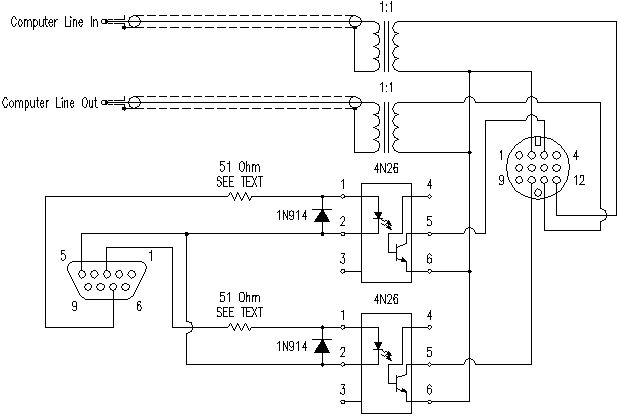
This document outlines a modification that connects a radio to a computer. It is important to proceed with caution and recognize that the responsibility for any consequences lies with the user. The design has been tested on an Icom...
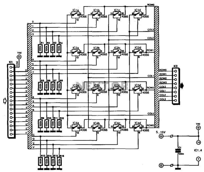
Keyboards can be classified into two categories based on the connection method of the switches: those with a common connection and those arranged in a matrix. The matrix type offers the significant advantage of minimizing the number of connections,...
SPI stands for Serial Peripheral Interface, which is the simplest among all communication protocols. Eight-bit data registers in the devices are connected by wires. These data registers function as shift registers, with one device controlling the data exchange within...
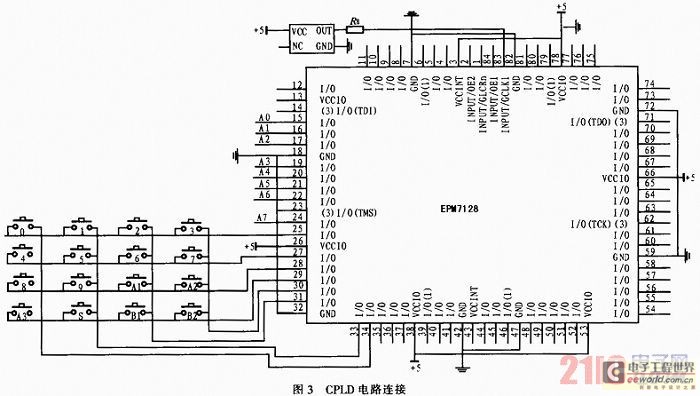
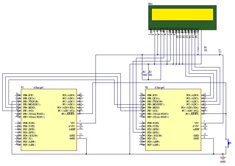
The system utilizes a modular design featuring the AT89S52 microcontroller and CPLD as the central processing unit (CPU) for overall system coordination. Initially, it establishes a cycle of systematic pulse signals through a 4G-4 key set module, allowing for...