
Very low frequency active filter 5G28 schematic

The fourth-order Butterworth low-pass filter is characterized by its maximally flat frequency response in the passband, making it suitable for applications where preserving the amplitude characteristics of the input signal is crucial. The design utilizes a combination of operational amplifiers and passive components, specifically resistors and capacitors, to achieve the desired filtering effect.
In this configuration, the filter's cut-off frequency is determined by the values of the resistors and the capacitor used in the circuit. The choice of a 1 µF capacitor is particularly important as it allows for a precise tuning of the cut-off frequency, ensuring that the filter effectively attenuates frequencies above 8 Hz while maintaining the integrity of the signals within the passband. The use of metal film precision resistors contributes to the overall stability and reliability of the filter, providing minimal thermal drift and low noise characteristics.
The intrinsic attenuation of 0.467 in the passband indicates that the filter will allow signals to pass with minimal loss, which is essential in applications requiring high fidelity. The input resistance of approximately 40 kΩ ensures that the filter can be interfaced with various signal sources without significantly affecting their output impedance.
Overall, this fourth-order Butterworth low-pass active filter is well-suited for applications involving the suppression of unwanted VLF noise while preserving the desired signal quality, making it an effective solution in various electronic systems. As shown in FIG staggering low frequency active filter circuit. This is a fourth-order Butterworth low-pass active filters for filtered VLF random pulse noise voltage DC level signal on its cut-off frequency (-3dB) about 8Hz, at 18Hz at 20dB gain reduction. Intrinsic attenuation in the passband of 0.467. Input resistance is approximately 40k. Filter network using a number of resistors are metal film precision resistor in series. If one 1 F capacitor to achieve a considerable accuracy, the cutoff frequency fc close to the theoretical value.
Related Circuits
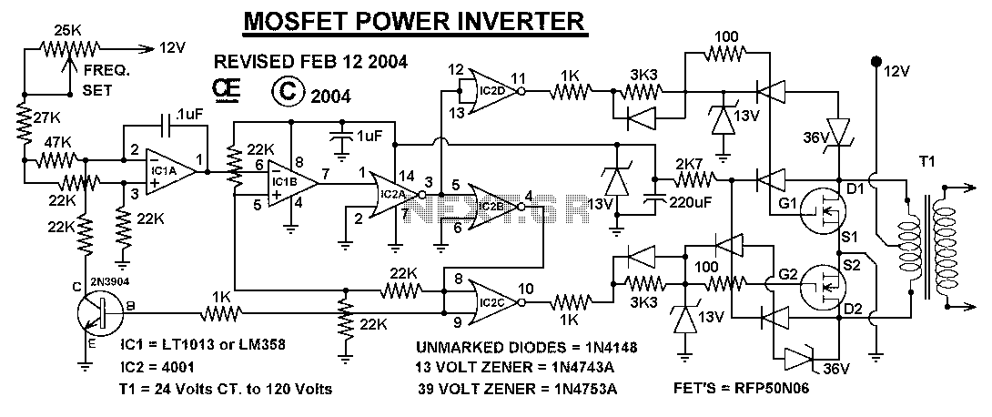
This power inverter circuit provides a stable square wave output voltage. The frequency of operation is set by a potentiometer and is typically adjusted to 60 Hz. Various off-the-shelf transformers can be utilized, or custom-wound transformers can be created...
The hum noise is produced by an electronic device with improper design. To address this issue, it is essential to identify the source of the hum. This involves checking the grounding, cabling, casing, and other factors that may contribute...
The transmitter circuit for inductive headphones must be installed on a wall or ceiling, limiting their use outdoors. This is a significant drawback of inductive headphones. In contrast, infrared wireless headphones do not have this limitation; their flexible infrared...
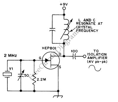
This is an oscillator circuit designed for calibrating frequency counters, amateur receivers, and frequency meters. It is referred to as the 2MHz standard with dividers circuit. The circuit utilizes two crystals, one at 100kHz and another at 2MHz. The...
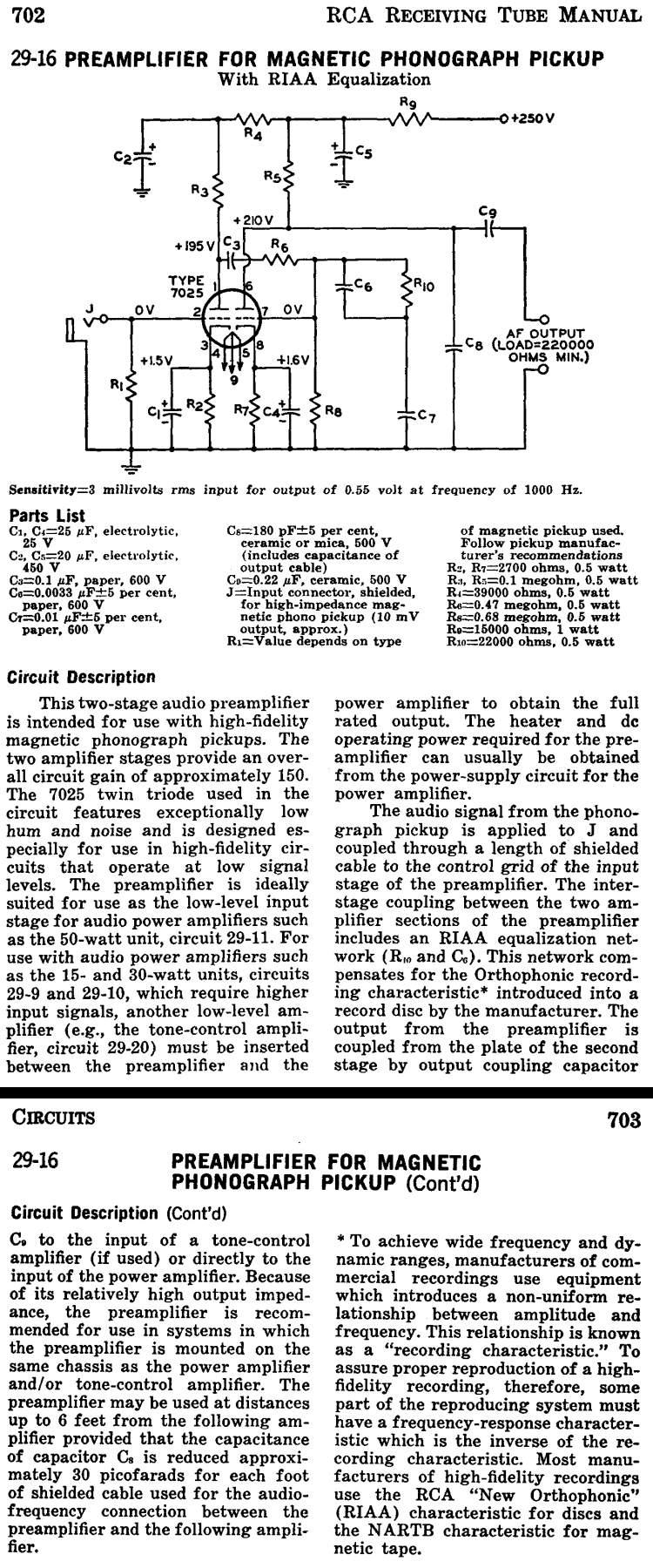
This two-stage audio preamplifier is designed for high-fidelity magnetic phonograph pickups, providing an overall gain of approximately 150. The circuit is sourced from the RCA tube receiving manual and is intended for use with the renowned RCA 7025 twin...
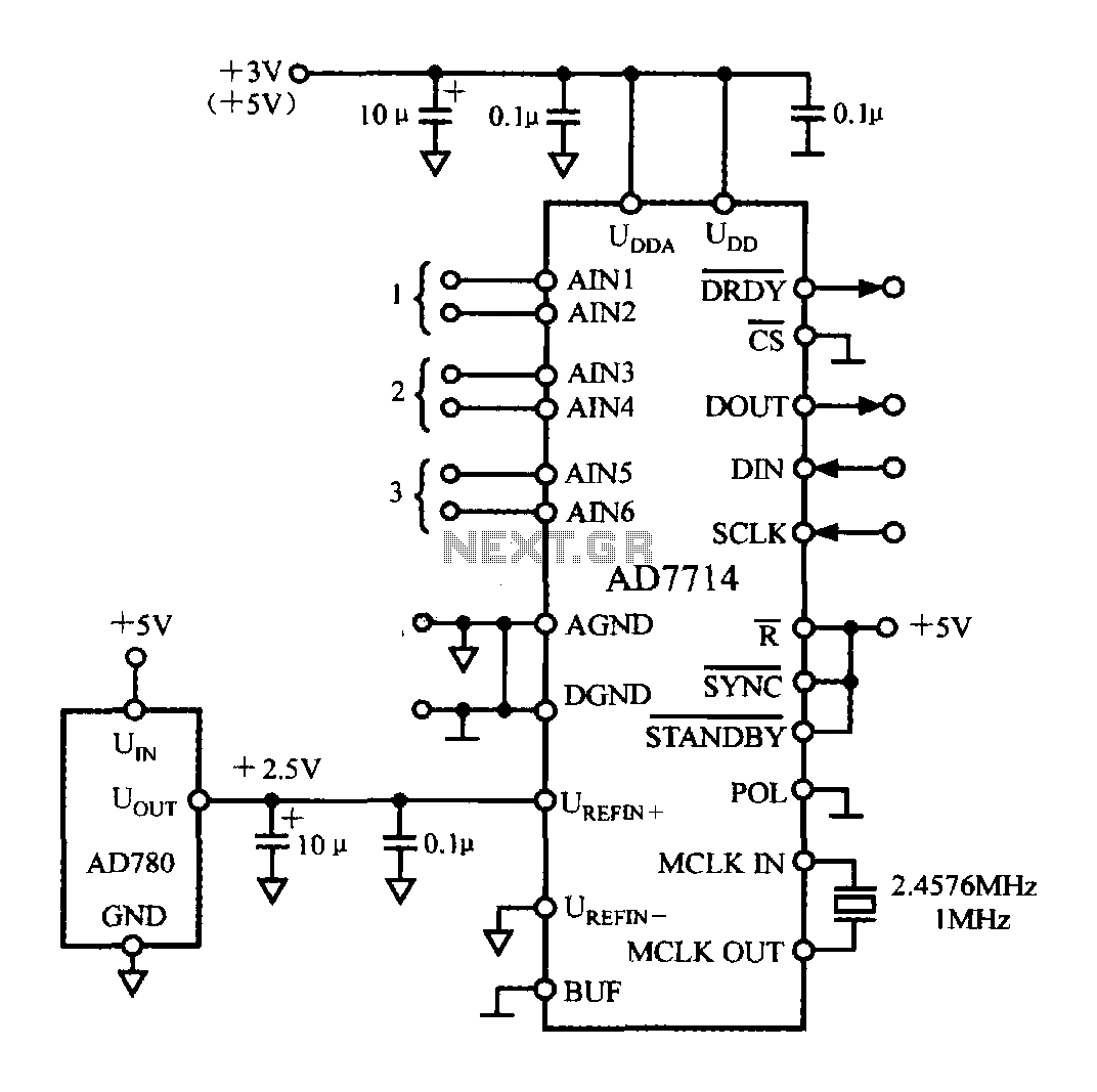
The typical application circuit for the AD7714 is illustrated in the accompanying figure. The UDD and UDDA terminals of the AD7714 can be connected to either a +3V or +5V power supply. The analog inputs are arranged as three...